I/O outputs
-
Hello
I want to connect a PLC to the DUET2 board and I would need to know if it has digital outputs.
In the datasheet I have seen that there are PWM outputs and then I/O, but I am not sure if the last ones are digital inputs/outputs.Thank you,
-
@amimafe they are digital inputs/outputs, however the output signal level is 3.3V whereas PLCs typically expect 24V open-collector/open-drain outputs. So not directly compatible.
The inputs can be connected directly to NPN outputs of a PLC, or to PNP outputs indirectly using two resistors. It's the same as when you connect an NPN or PNP output sensor to a Duet input, which is covered in the wiki.
The 6XD main board has 4 optically isolated inputs and outputs that can be connected directly to PLCs.
Duet WiFi hardware designer and firmware engineer
Please do not ask me for Duet support via PM or email, use the forum
http://www.escher3d.com, https://miscsolutions.wordpress.com -
@dc42 Thanks for your help.
We are going to use optocouplers to be able to adapt the input and output signals.
I need 5 output signals (I was thinking of using the STEP ones) and 3 input signals (I don't know which ones yet).
Do the digital inputs/outputs have to be configured to be used as input or output?Thanks again.
-
-
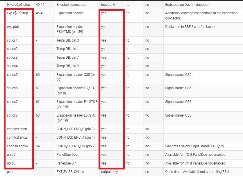
@amimafe for more detail about what each pin can be used for, see the pin capability column in the pin table that starts at line 261 of https://github.com/Duet3D/RepRapFirmware/blob/3.4-dev/src/Config/Pins_DuetNG.h.
Duet WiFi hardware designer and firmware engineer
Please do not ask me for Duet support via PM or email, use the forum
http://www.escher3d.com, https://miscsolutions.wordpress.com -
This post is deleted! -
@dc42 Thank you for your help.
Finally I selected other i/o pins and got the expected results.
As part of the project I have to design a rotating nozzle and I have seen that there are options to define an axis as rotating.
What I have not been able to figure out is how to create a dependency of this axis with the movement of the X and Y axes. I want the nozzle to rotate following the print path.
I had thought about using the atan2 function, but I don't know how to implement it, maybe with a macro? -
@amimafe can you explain your requirements in more detail?
If you are looking to rotate the nozzle to be always at the same angle to the print path, this has been done before by preprocessing the GCode.
Duet WiFi hardware designer and firmware engineer
Please do not ask me for Duet support via PM or email, use the forum
http://www.escher3d.com, https://miscsolutions.wordpress.com -
@dc42 hello again,
I need to develop a nozzle with 2 rotating blades for a ceramic printer. What I need is that while the machine is printing these blades rotate according to the trajectory it takes and smooth the walls.
Do you have any idea how I could implement the movement of this motor? I had thought of making a macro with the function atan2 to calculate the tangent of the X and Y axes and get the angle of rotation. I am not sure if this is possible.
Thanks
-
@amimafe the simplest solution would be to write a script to preprocess the GCode. You will have some decisions to make; for example, when there is an abrupt change in direction, do you want to stop the XY movement, rotate the nozzle, and restart the XY movement? Or do you want to perform the nozzle rotation at the start of the second segment; in which case, over what distance do you want to complete the nozzle rotation?
Duet WiFi hardware designer and firmware engineer
Please do not ask me for Duet support via PM or email, use the forum
http://www.escher3d.com, https://miscsolutions.wordpress.com -
@dc42 Ok. We plan to eliminate the right angles by curves with a minimum radius so that the blades do not damage the print.
I have made some progress on the project and am now testing the rotational axis on a nema17. I have noticed that if I don't set a limit of movement with the M208 command, the firmware limits me to 200 microsteps. Is there any way to remove this limit?
I have not found much information about the configuration of the rotational axes.Thank you!
-
@amimafe said in I/O outputs:
I have noticed that if I don't set a limit of movement with the M208 command, the firmware limits me to 200 microsteps.
The default axis limits are 0 to 200mm, or 0 to 200 degrees for rotary axis. You can use M208 to set the limits as high as you like, provided that you don't exceed +/- 2^31 microsteps.
Duet WiFi hardware designer and firmware engineer
Please do not ask me for Duet support via PM or email, use the forum
http://www.escher3d.com, https://miscsolutions.wordpress.com -
@dc42 Hi!!
I was finally able to find a solution for the nozzle movement and we are moving forward with the project.
But now we have another problem. When our device performs curved movements it makes micro-stops.
We have adjusted the JERK and the accelerations and it improves the movement, but would there be a way to make duet disregard some angles or segments and perform the movement without stopping?
I have searched for information on this topic but can't find anything consistent.
Any idea?Thanks!
-
@amimafe it sound to me that you still have the XY jerk values set too low.
Duet WiFi hardware designer and firmware engineer
Please do not ask me for Duet support via PM or email, use the forum
http://www.escher3d.com, https://miscsolutions.wordpress.com -
I thought the same thing at the beginning but I have tried different jerk values (from 0 to 300mm/s) with different accelerations and although it improves the movements with high jerks, it still stutters a little bit.
Is there any way to avoid deceleration at certain angles?
Our printer has a size of 3.5m for the Y axis and 2.5m for the X axis. In case this information is useful. -
 undefined amimafe marked this topic as a question
-
undefined amimafe has marked this topic as solved