CNC - Using R68 for rotated stock pieces
-
Hi,
I've been trying to research this and work it out for myself but I'm a little confused so I wondered if anyone here is able to help.
Apologies for any naïve understanding or use of terminologies in advance!The Problem
I would like to clamp-down a square stock piece to the spoil board and let a suitable probing procedure determine the origin and angle of the stock piece and to adjust the coordinate system accordingly.What I understand so far
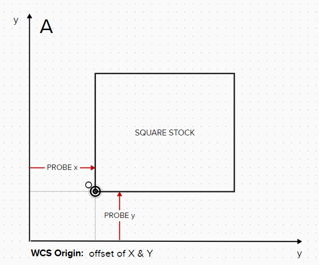
A. Using a probe, I can easily determine the WCS origin of a square stock piece that is perpendicular to the CNC x & y axes (I use G38.2... & G10...). I have already implemented this and use it all the time.
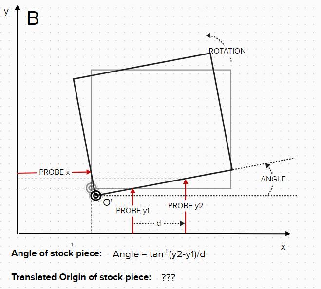
B. By probing the square stock piece in 2 locations along the x-axis I can calculate the angle of the stock piece from the difference in 'y'. I have tested a macro code for this and it gives the correct angle result.
So, my questions are:-
Using this angle, how can I calculate the true WCS origin of the stock piece (ie, the origin calculated in A will no longer be correct due to the rotation/translation)?
-
What coordinates do I use for A & B in the GCODE R68 Annn Bnnn Rnnn in this scenario?
I realise I can just position the stock as square as possible and it would probably be fine but, since R68 is implemented in RRF, I'd like to understand how to use it.
I welcome any (simplified!) useful information around this if anyone uses it on their Duet/RRF machines?
Many thanks,
Jason
-
-
@greeno76 Did you find a solution to your question? I would also like to better understand how to do this as well. Moreover, I would like to know how to adjust the WCS for reworking a part. That is, after I have machined a part and removed it from the table I may decide that I want to add some features and machine the part further. So, I need a way to align the WCS with the part.
-
@steve123 @greeno76 if the 3 probe positions have coordinates x0,y0 (the one of the left of the part), x1,y1 and x2,y2 then:
Let t = (y2 - y1)/(x2 - x1)
then angle = arctan(t) as you said already.Let the origin O' be at (x,y). Then we have the following (solved using wxMaxima, but it's just a pair of simultaneous equations so not difficult to do by hand):
        eqn_1:x-x0=t*(y0-y);
(eqn_1)	x-x0=t*(y0-y)
	eqn_2:y2-y=t*(x2-x);
(eqn_2)	y2-y=t*(x2-x)
	eqn_3:solve(eqn_2,y);
(eqn_3)	[y=y2-t*x2+t*x]
	eqn_4:subst(eqn_3,eqn_1);
(eqn_4)	x-x0=t*(-y2+y0+t*x2-t*x)
	eqn_5:solve(eqn_4,x);
(eqn_5)	[x=-((t*y2-t*y0-t^2*x2-x0)/(t^2+1))]
	eqn_6:subst(eqn_5,eqn_3);
(eqn_6)	[y=-((t*(t*y2-t*y0-t^2*x2-x0))/(t^2+1))+y2-t*x2]
The first equation assumes that the angle at O' is a right angle.
Please test this before you rely on it!
Duet WiFi hardware designer and firmware engineer
Please do not ask me for Duet support via PM or email, use the forum
http://www.escher3d.com, https://miscsolutions.wordpress.com -
@dc42 Thank you. The math looks good. I will try it out.
In the mean time I used a couple blocks to align the part to the x and y axis and then found zero using the edges of the part. It would be great to have a macro that allows you to place the part/stock and then adjust the machine using the edges without having to do the manual alignment. Assuming you have a couple straight edges perpendicular to each other. Another handy thing would be a macro to flip the part if you need to machine both sides of the part. Is there a G code that allows you to mirror one of the WCS axis?