Duet3D Logo Duet3D
    • Tags
    • Documentation
    • Order
    • Register
    • Login
    1. Home
    2. greeno76
    • Profile
    • Following 0
    • Followers 0
    • Topics 4
    • Posts 10
    • Best 2
    • Controversial 0
    • Groups 0

    greeno76

    @greeno76

    2
    Reputation
    1
    Profile views
    10
    Posts
    0
    Followers
    0
    Following
    Joined Last Online

    greeno76 Unfollow Follow

    Best posts made by greeno76

    • RE: Duet 3 Mini + RPI4 + Touchscreen HDMI 7"

      Hi,

      Thanks for your suggestion. I tried separate power supplies for all devices but unfortunately the issue still persisted.

      Given that this is an as-yet unconnected system I've simply started from scratch and reinstalled the DuetPi img. The Duet3 mini board has successfully connected. I have since configured the HDMI touchscreen and Camera and the Duet3 is still connecting fine.

      So, I'm not sure what I learned there!, Slightly concerning but hopefully it'll be fine if I don't meddle too much and I can go ahead and start wiring-up and configuring the CNC.

      Many thanks for your replies.

      Best wishes,

      Jason

      posted in General Discussion
      greeno76undefined
      greeno76
    • RE: Duet 3 Mini + RPI4 + Touchscreen HDMI 7"

      @phaedrux I should clarify in case its misleading for anyone in the future.

      The original DuetPi image was downloaded from the official GitHub location as was the last install which appeared to solve my problem.

      I think I must have bodged the HDMI screen installation tbh. I ran some install command but really it just needed to be configured in config.txt.

      All seems to be working now. I've since upgraded to the 3.4 RC and I've successfully tested motion on the stepper motors.

      Thanks again.

      Jason

      posted in General Discussion
      greeno76undefined
      greeno76

    Latest posts made by greeno76

    • CNC - Using R68 for rotated stock pieces

      Hi,

      I've been trying to research this and work it out for myself but I'm a little confused so I wondered if anyone here is able to help.
      Apologies for any naïve understanding or use of terminologies in advance!

      The Problem
      I would like to clamp-down a square stock piece to the spoil board and let a suitable probing procedure determine the origin and angle of the stock piece and to adjust the coordinate system accordingly.

      What I understand so far
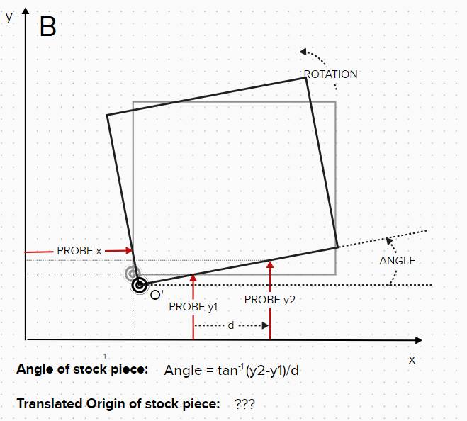
      A. Using a probe, I can easily determine the WCS origin of a square stock piece that is perpendicular to the CNC x & y axes (I use G38.2... & G10...). I have already implemented this and use it all the time.
      bd4f5c98-675f-468c-ad7b-bc5d9aefddbf-image.png
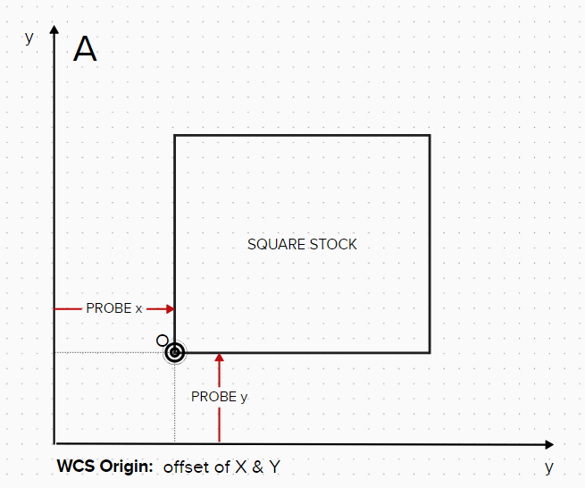
      B. By probing the square stock piece in 2 locations along the x-axis I can calculate the angle of the stock piece from the difference in 'y'. I have tested a macro code for this and it gives the correct angle result.
      12e53937-9eb3-41cc-8f61-f1ca8f6daeac-image.png
      So, my questions are:

      • Using this angle, how can I calculate the true WCS origin of the stock piece (ie, the origin calculated in A will no longer be correct due to the rotation/translation)?

      • What coordinates do I use for A & B in the GCODE R68 Annn Bnnn Rnnn in this scenario?

      I realise I can just position the stock as square as possible and it would probably be fine but, since R68 is implemented in RRF, I'd like to understand how to use it.

      I welcome any (simplified!) useful information around this if anyone uses it on their Duet/RRF machines?

      Many thanks,

      Jason

      posted in CNC cnc milling rotation r68 gcode maths
      greeno76undefined
      greeno76
    • RE: SD Card Dead after upgrade. Recovery Options?

      This might provide a possible solution. https://github.com/rclone/rclone ??

      Definitely want to avoid having to reinstall everything again in the event of an SD card failure!

      posted in CNC
      greeno76undefined
      greeno76
    • RE: SD Card Dead after upgrade. Recovery Options?

      @phaedrux OK, thank you. I thought that was probably the case. As I said, the config file is in one of my previous forum questions so I think I can just use that.

      Sadly I have no record of the macros (touchplate WCS setting) but I'll work through those and get it up and running again asap.

      Best wishes,

      Jason

      posted in CNC
      greeno76undefined
      greeno76
    • RE: SD Card Dead after upgrade. Recovery Options?

      ...it's some consolation that I've previously posted my config.g file on this forum.

      I've just checked to see if I had an SD card in the Duet board but it seems not, so I guess the only question here is what are the back-up options for next time.... 😢

      J

      posted in CNC
      greeno76undefined
      greeno76
    • SD Card Dead after upgrade. Recovery Options?

      Hi,

      I try to update the Pi and the Duet board regularly (unstable branch) and it's been running pretty well for most of this year now. However, after upgrading the Raspi/Duet yesterday (9/9/22)my system has crashed and will now not boot. It was actually running after the update as was able to connect to the web interface over my network but seems to have died since.

      When powered up the RPi4 only shows 1 red LED with no other activity so I understand that this is most likely an SD card corruption issue. The SD Card is a Sony 64GB Class 10 FWIW.

      I've tried to attach the SD card to a couple of computers but it won't mount at all - repeated windows mount/unmount beeps. Same behaviour on a Chromebook. So, this, I think, confirms my suspicions that it's an SD card issue.

      If that IS the case, what are the recovery options for the system as a whole (various SD card recovery techniques have not worked or are not applicable thus far) ?

      If I write a new Raspi Duet image on a new SD card and (assuming the Pi4 isn't actually damaged), load it onto the Pi4 (usual wifi config etc) should I expect it to reconnect with the Duet board without too much faff or am I likely to need to have to start from scratch. I don't know if any of my config/macro files are stored on the board itself.

      I'm guessing that this is a lesson in backing-up files so I would also be interested in knowing a good approach for this. I run a Homeassistant instance on another raspberry pi and recovery from google cloud backups is very well implemented such that it's very reassuring that I won't have to set it all from scratch in the [likely] event of SD card failure. Is there a cloud backup mechanism for Duet/Pi?

      It's a little frustrating as it was all a bit of a learning curve setting it up and, I must admit, I've forgotten a lot of it so I'm anticipating another ride on the learning curve ahead of me!

      Any experience or advice is welcome.

      Many thanks,

      Jason (Bedford, UK)
      posted in CNC
      greeno76undefined
      greeno76
    • Duet3/Raspi CNC G29 at WCS Zero

      Hi,

      I'm trying to mill PCBs and I anticipate that the small and inevitable variations in material thickness and bed levelness will make it difficult to achieve a decent result without some bed level compensation. I'm familiar with this process on a 3D printer where the offsets are usually constant assuming the probe is attached to the extruder.

      However when using the G29 command with the CNC, the machine appears to use the M557 mesh coordinates as absolute values from Machine zero, rather than the WCS Zero. Hopefully that makes sense. I'm relatively new to the language of CNC!

      I wonder if anyone could kindly clarify whether it's possible to:

      1. Zero the machine to its limits as usual
      2. Set the WCS Zero at stock top (or appropriate reference point)
      3. Issue Mesh bed probe G29
      4. Machine probes coordinates set in M557 relative to the WCS offset
      5. Machine uses mesh for bed compensation during milling operation.

      I've tried a couple of times and narrowly avoided certain death of my end-mill diving into the spoil board at Machine X0Y0. Just wondering if there's a solution to this that doesn't involve hard-coding offsets in the config files?

      Config.g below for reference.

      Any help appreciated, thank you. Jason

      ; Configuration file for Duet 3 Mini 5+ (firmware version 3.3)
      ; executed by the firmware on start-up
      ;
      ; generated by RepRapFirmware Configuration Tool v3.3.10 on Thu Feb 17 2022 16:48:19 GMT+0000 (Greenwich Mean Time)
      
      ; General preferences
      G90                                     ; send absolute coordinates...
      M83                                     ; ...but relative extruder moves
      M550 P"Duet 3"                          ; set printer name
      
      ; Drives
      M569 P0.0 S0                            ; physical drive 0.0 goes forwards
      M569 P0.1 S1                            ; physical drive 0.1 goes forwards
      M569 P0.2 S1                            ; physical drive 0.2 goes forwards
      M569 P0.3 S0                            ; physical drive 0.3 goes forwards
      M569 P0.4 S1                            ; physical drive 0.4 goes forwards
      
      M584 X0.0:0.1 Y0.2:0.3 Z0.4            ; set drive mapping
      
      M350 X16 Y16 Z16 I1                    ; configure microstepping with interpolation
      M92 X80.00 Y80.00 Z400.00              ; set steps per mm
      M566 X900.00 Y900.00 Z60.00            ; set maximum instantaneous speed changes (mm/min)
      M203 X6000.00 Y6000.00 Z180.00         ; set maximum speeds (mm/min)
      M201 X500.00 Y500.00 Z20.00            ; set accelerations (mm/s^2)
      M906 X1200 Y1200 Z1200 I30             ; set motor currents (mA) and motor idle factor in per cent
      M84 S30                                ; Set idle timeout
      
      ; Axis Limits
      M208 X0 Y0 Z0 S1                        ; set axis minima
      M208 X600 Y330 Z81 S0                   ; set axis maxima
      
      ; Endstops
      M574 X1 S1 P"!io0.in+!io1.in"          ; configure switch-type (e.g. microswitch) endstop for low end on X via pin io0.in
      M574 Y1 S1 P"!io2.in+!io3.in"
      ; M574 Y1 S4                           ; configure switch-type (e.g. microswitch) endstop for low end on Y via pin io1.in
      ;M574 Z1 S1 P"!io4.in"                  ; configure switch-type (e.g. microswitch) endstop for low end on Z via pin io4.in
      ; M915 X Y R0 F0
      
      ; CNC Specific
      M950 R0 C"OUT_0" L12000                ; Create spindle index 0, with PWM pin on heater 3 and 12000 RPM achieved at full PWM
      M563 P1 S"Spindle 1" R0                ; Create tool 1 with spindle 0 and call it "Spindle 1"
      M453
      
      ; Z-Probe
      M558 P5 C"!io4.in" H5 F120 T3000         ; set Z probe type to switch and the dive height + speeds
      G31 P500 X0 Y0 Z0                    ; set Z probe trigger value, offset and trigger height
      M557 X5:100 Y5:100 S10 					; Define mesh grid   
      
      ; Heaters
      M140 H-1                                ; disable heated bed (overrides default heater mapping)
      
      ; Fans
      M950 F0 C"out3" Q500                    ; create fan 0 on pin out3 and set its frequency
      M106 P0 S0 H-1                          ; set fan 0 value. Thermostatic control is turned off
      M950 F1 C"out4" Q500                    ; create fan 1 on pin out4 and set its frequency
      M106 P1 S1 H T45                        ; set fan 1 value. Thermostatic control is turned on
      
      ; Tools
      
      ; Custom settings are not defined


      posted in General Discussion
      greeno76undefined
      greeno76
    • RE: Duet 3 Mini + RPI4 + Touchscreen HDMI 7"

      @phaedrux I should clarify in case its misleading for anyone in the future.

      The original DuetPi image was downloaded from the official GitHub location as was the last install which appeared to solve my problem.

      I think I must have bodged the HDMI screen installation tbh. I ran some install command but really it just needed to be configured in config.txt.

      All seems to be working now. I've since upgraded to the 3.4 RC and I've successfully tested motion on the stepper motors.

      Thanks again.

      Jason

      posted in General Discussion
      greeno76undefined
      greeno76
    • RE: Duet 3 Mini + RPI4 + Touchscreen HDMI 7"

      Hi,

      Thanks for your suggestion. I tried separate power supplies for all devices but unfortunately the issue still persisted.

      Given that this is an as-yet unconnected system I've simply started from scratch and reinstalled the DuetPi img. The Duet3 mini board has successfully connected. I have since configured the HDMI touchscreen and Camera and the Duet3 is still connecting fine.

      So, I'm not sure what I learned there!, Slightly concerning but hopefully it'll be fine if I don't meddle too much and I can go ahead and start wiring-up and configuring the CNC.

      Many thanks for your replies.

      Best wishes,

      Jason

      posted in General Discussion
      greeno76undefined
      greeno76
    • RE: Duet 3 Mini + RPI4 + Touchscreen HDMI 7"

      Thanks both for kindly replying.

      Regarding the power, the Pi4 has its own Raspberry Pi branded power supply. The 7" HDMI touchscreen is powered via USB to the Raspberry Pi.

      The Duet3 mini is powered by it's own USB supply. Jumpers haven't been changed so should be in their default potision. The board is not yet connected to any motors or sensors. I've only had it running with the RPi for testing and basic config purposes so far.

      The RPi also has a camera connected via the Camera interface running mpeg-streamer. This was running fine along with DCS before the HDMI screen was installed.

      The RPi is running the 3.3 version software as you can see in the output above. It's the Duet IMG downloaded from the official repo. I haven't altered it, aside from running apt-get update/upgrade, installing mpeg-streamer and now sudo ./ LCD7-1024x600-show X, which I think appends the config.txt file with the HDMI info in the root filesystem.

      FYI, Touchscreen is this one: Link to HDMI on Pi Hut. Here's the manual for the screen for reference.
      7inch_HDMI_LCD_User_Manual_EN.pdf

      I've copied the output from sudo gpioinfo below. I'm not sure how to interpret it. Perhaps you can see some conflicted pins here?

      pi@duet3:~ $ gpioinfo
      gpiochip0 - 58 lines:
              line   0:     "ID_SDA"       unused   input  active-high
              line   1:     "ID_SCL"       unused   input  active-high
              line   2:       "SDA1"       unused   input  active-high
              line   3:       "SCL1"       unused   input  active-high
              line   4:  "GPIO_GCLK"       unused   input  active-high
              line   5:      "GPIO5"       unused   input  active-high
              line   6:      "GPIO6"       unused   input  active-high
              line   7:  "SPI_CE1_N"   "spi0 CS1"  output   active-low [used]
              line   8:  "SPI_CE0_N"   "spi0 CS0"  output   active-low [used]
              line   9:   "SPI_MISO"       unused   input  active-high
              line  10:   "SPI_MOSI"       unused   input  active-high
              line  11:   "SPI_SCLK"       unused   input  active-high
              line  12:     "GPIO12"       unused   input  active-high
              line  13:     "GPIO13"       unused   input  active-high
              line  14:       "TXD1"       unused   input  active-high
              line  15:       "RXD1"       unused   input  active-high
              line  16:     "GPIO16"       unused   input  active-high
              line  17:     "GPIO17"       unused   input  active-high
              line  18:     "GPIO18"       unused   input  active-high
              line  19:     "GPIO19"       unused   input  active-high
              line  20:     "GPIO20"       unused   input  active-high
              line  21:     "GPIO21"       unused   input  active-high
              line  22:     "GPIO22"       unused   input  active-high
              line  23:     "GPIO23"       unused   input  active-high
              line  24:     "GPIO24"       unused   input  active-high
              line  25:     "GPIO25" "ads7846_pendown" input active-high [used]
              line  26:     "GPIO26"       unused   input  active-high
              line  27:     "GPIO27"       unused   input  active-high
              line  28: "RGMII_MDIO"       unused   input  active-high
              line  29:  "RGMIO_MDC"       unused   input  active-high
              line  30:       "CTS0"       unused   input  active-high
              line  31:       "RTS0"       unused   input  active-high
              line  32:       "TXD0"       unused   input  active-high
              line  33:       "RXD0"       unused   input  active-high
              line  34:    "SD1_CLK"       unused   input  active-high
              line  35:    "SD1_CMD"       unused   input  active-high
              line  36:  "SD1_DATA0"       unused   input  active-high
              line  37:  "SD1_DATA1"       unused   input  active-high
              line  38:  "SD1_DATA2"       unused   input  active-high
              line  39:  "SD1_DATA3"       unused   input  active-high
              line  40:  "PWM0_MISO"       unused   input  active-high
              line  41:  "PWM1_MOSI"       unused   input  active-high
              line  42: "STATUS_LED_G_CLK" "led0" output active-high [used]
              line  43: "SPIFLASH_CE_N" unused input active-high
              line  44:       "SDA0"       unused   input  active-high
              line  45:       "SCL0"       unused   input  active-high
              line  46: "RGMII_RXCLK" unused input active-high
              line  47: "RGMII_RXCTL" unused input active-high
              line  48: "RGMII_RXD0"       unused   input  active-high
              line  49: "RGMII_RXD1"       unused   input  active-high
              line  50: "RGMII_RXD2"       unused   input  active-high
              line  51: "RGMII_RXD3"       unused   input  active-high
              line  52: "RGMII_TXCLK" unused input active-high
              line  53: "RGMII_TXCTL" unused input active-high
              line  54: "RGMII_TXD0"       unused   input  active-high
              line  55: "RGMII_TXD1"       unused   input  active-high
              line  56: "RGMII_TXD2"       unused   input  active-high
              line  57: "RGMII_TXD3"       unused   input  active-high
      gpiochip1 - 8 lines:
              line   0:      "BT_ON"       unused  output  active-high
              line   1:      "WL_ON"       unused  output  active-high
              line   2: "PWR_LED_OFF" "led1" output active-low [used]
              line   3: "GLOBAL_RESET" unused output active-high
              line   4: "VDD_SD_IO_SEL" "vdd-sd-io" output active-high [used]
              line   5:   "CAM_GPIO"       unused  output  active-high
              line   6:  "SD_PWR_ON" "sd_vcc_reg"  output  active-high [used]
              line   7:    "SD_OC_N"       unused   input  active-high
      

      I'm a bit stuck. Is it worth me trying to reinstall the Duet software?

      Once again, any help is hugely appreciated.

      Thanks again,

      Jason

      posted in General Discussion
      greeno76undefined
      greeno76
    • Duet 3 Mini + RPI4 + Touchscreen HDMI 7"

      Hi,

      I've successfully set-up my new Duet3 mini with a Raspberry Pi 4 and all seemed to be working fine. I'm excited to install this control system into a new CNC router asap (I have a Duet2 wifi in my 3D printer which works beautifully).

      This evening I've added the Waveform 7" HDMI touchscreen and I'm now getting the error, "Failed to connect to Duet3.home. Failed to connect to Duet, please check your connection (DCS is not started)".

      I've searched the forums for similar issues but I haven't found anything yet. I've run the command, "sudo journalctl -u duetcontrolserver -e" which gave the following log.

      Feb 15 19:00:51 duet3 systemd[1]: Starting Duet Control Server...
      Feb 15 19:00:52 duet3 DuetControlServer[8331]: Duet Control Server v3.3.0
      Feb 15 19:00:52 duet3 DuetControlServer[8331]: Written by Christian Hammacher for Duet3D
      Feb 15 19:00:52 duet3 DuetControlServer[8331]: Licensed under the terms of the GNU Public License Version 3
      Feb 15 19:00:53 duet3 DuetControlServer[8331]: [info] Settings loaded
      Feb 15 19:00:53 duet3 DuetControlServer[8331]: [info] Environment initialized
      Feb 15 19:00:53 duet3 DuetControlServer[8331]: [fatal] Could not connect to Duet (Error 16. Cannot put line into event mode.)
      Feb 15 19:00:53 duet3 systemd[1]: duetcontrolserver.service: Failed with result 'protocol'.
      Feb 15 19:00:53 duet3 systemd[1]: Failed to start Duet Control Server.
      Feb 15 19:00:53 duet3 systemd[1]: duetcontrolserver.service: Service RestartSec=100ms expired, scheduling restart.
      Feb 15 19:00:53 duet3 systemd[1]: duetcontrolserver.service: Scheduled restart job, restart counter is at 692.
      Feb 15 19:00:53 duet3 systemd[1]: Stopped Duet Control Server.
      Feb 15 19:00:53 duet3 systemd[1]: Starting Duet Control Server...
      Feb 15 19:00:53 duet3 DuetControlServer[8369]: Duet Control Server v3.3.0
      Feb 15 19:00:53 duet3 DuetControlServer[8369]: Written by Christian Hammacher for Duet3D
      Feb 15 19:00:54 duet3 DuetControlServer[8369]: Licensed under the terms of the GNU Public License Version 3
      Feb 15 19:00:54 duet3 DuetControlServer[8369]: [info] Settings loaded


      There is clearly an error in there ( "Could not connect to Duet (Error 16. Cannot put line into event mode.") but I don't know how to overcome it. Can anyone help me, please? Is there a code / pin conflict going on?

      Any help appreciated!

      Many thanks, Jason (UK)

      posted in General Discussion
      greeno76undefined
      greeno76