5bar scara Problem configuring z probe using fsr switch
-
@gnmrc_ said in Problem configuring z probe using fsr switch:
@fcwilt so I tried to position the arm to the home position and input the offsets manually with g92, now if I move the arm to the 0,0 position it works as it should.
If in the homing file I add a g92 x0 y0 than move the arm it should work, for sure is not the cleanest solution but seems reasonable.
Tell me what you think.Gianmarco
I tried this solution using first s2 and that h0 but it does not work.
with h0 it does not work and with s2 it overshoots as before. -
@gnmrc_ said in Problem configuring z probe using fsr switch:
@fcwilt so I tried to position the arm to the home position and input the offsets manually with g92, now if I move the arm to the 0,0 position it works as it should.
If in the homing file I add a g92 x0 y0 than move the arm it should work, for sure is not the cleanest solution but seems reasonable.
Tell me what you think.Gianmarco
I only use G92 during testing and in my homing files.
For example:
Let's say my bed is 300 x 300. But I like to have X=0, Y=0 at the center of that area. So the printable limits of the X axis are specified in M208 as -150 and 150.
But my endstop is actually at -175.
So when doing a typical homing move...
G91              ; relative moves
G1 H1 X-399 F600 ; move toward the endstop
...when the endstop is activated the behavior of the H1 move is to set the logical X axis position to Xmin as specified in the M208, which as mentioned above is -150.
But the physical position is -175 because that is where movement stops when the endstop was triggered.
We now have a situation where the logical position of -150 is out of sync with the physical position of -175.
So to get them in sync I do something like:
M564 S0      ; ignore axis limits
G90          ; absolute move
G1 X175 F600 ; move to physical position X=0
G92 X0       ; set logical position to X=0
M564 s1      ; respect axis limits
Now things are in sync. I usually find that the X175 is a bit off and needs repeated testing to tweak the value so X=0 is just where I want it.
There are other ways to do this but this is how I do it.
Frederick
-
@fcwilt I will give it a try but if I understood correctly it's not our case of error, because my movement limits are min:-250,-250 max:250,250 when the arm is homed I'm inside those limits.
I really can't understand what I'm doing wrong.
We also should open another forum discussion because we are talking a lot about a completely different topic that maybe could help others.Gianmarco
-
@gnmrc_ said in Problem configuring z probe using fsr switch:
@gnmrc_ said in Problem configuring z probe using fsr switch:
@fcwilt so I tried to position the arm to the home position and input the offsets manually with g92, now if I move the arm to the 0,0 position it works as it should.
If in the homing file I add a g92 x0 y0 than move the arm it should work, for sure is not the cleanest solution but seems reasonable.
Tell me what you think.Gianmarco
I tried this solution using first s2 and that h0 but it does not work.
with h0 it does not work and with s2 it overshoots as before.I'm still testing while changing some parts of the homing procedure, when the arm overshoots it does it in a way that looks like the arm is moving to 0,0 as if the Zero position was in the front left corner of the bed that has an area 200x200
-
@gnmrc_ said in Problem configuring z probe using fsr switch:
@fcwilt I will give it a try but if I understood correctly it's not our case of error, because my movement limits are min:-250,-250 max:250,250 when the arm is homed I'm inside those limits.
I really can't understand what I'm doing wrong.
We also should open another forum discussion because we are talking a lot about a completely different topic that maybe could help others.Gianmarco
I see in the config.g file that both X and Y range from -250 to +250.
But where do the endstops trigger on each axis? Are they exactly at 250?
Frederick
Printers: a E3D MS/TC setup and a RatRig Hybrid. Using Duet 3 hardware running 3.4.6
-
@fcwilt no well you have to consider that being a scara they work on the axis rotation, but the position is inside the reachable area. The home position is aroung x-168 y-98 (I give you rough number because I’m not home right now), so no they do not trigger precisely in that position.
Gianmarco
-
 undefined infiniteloop referenced this topic
-
@fcwilt said in Problem configuring z probe using fsr switch:
@gnmrc_ said in Problem configuring z probe using fsr switch:
@fcwilt I will give it a try but if I understood correctly it's not our case of error, because my movement limits are min:-250,-250 max:250,250 when the arm is homed I'm inside those limits.
I really can't understand what I'm doing wrong.
We also should open another forum discussion because we are talking a lot about a completely different topic that maybe could help others.Gianmarco
I see in the config.g file that both X and Y range from -250 to +250.
But where do the endstops trigger on each axis? Are they exactly at 250?
Frederick
So I didn’t understood this, no the arm position at home does not correspond to the are limits. -
@gnmrc_ said in Problem configuring z probe using fsr switch:
@fcwilt no well you have to consider that being a scara they work on the axis rotation, but the position is inside the reachable area. The home position is aroung x-168 y-98 (I give you rough number because I’m not home right now), so no they do not trigger precisely in that position.
Gianmarco
Hi,
When you say "home position" what do you mean. Maybe what you think of as "home" is different than what I think of as "home".
And how did you determine the values in your M669 command?
Thanks.
Frederick
-
@fcwilt so for me the home is the position in which the machine reach the endstops(this position is outside the are of printing) and it was determined in the design process. The value for m669 are taken by measures of the arm lenght and for the degrees by the design than I put the data in a geometry calculation program and found the other informations that i needed for the configuration.
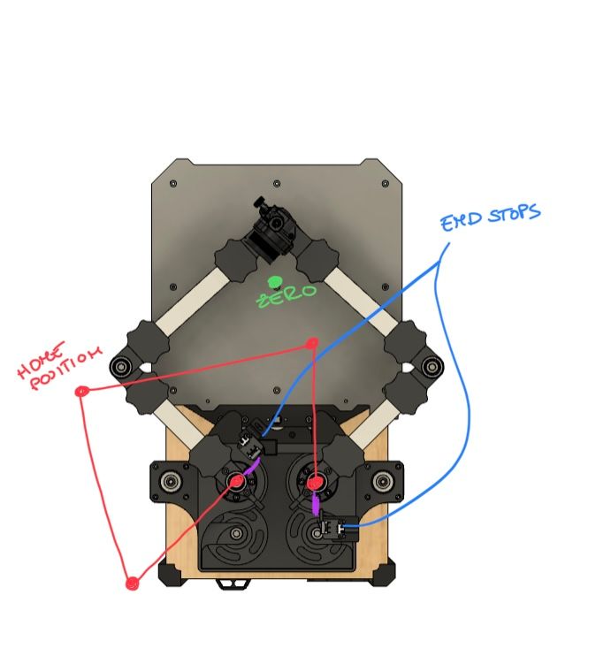
I made a simple sketch to explain me better
Gianmarco -
 undefined droftarts referenced this topic
-
That sketch helped a lot.
I would suggest you try this:
Execute...
M564 H0 S0 ; H0 = ignore axis homed state, S0 = ignore axes limits...then carefully jog X and Y to see if the physical position seems correct for various values of X and Y.
Once that seems to be working:
- carefully jog to where you want X=0 Y=0 to be
- execute a G92 X0 Y0 to set the logical positions of X and Y
- carefully jog X and Y until the endstop switches are activated (there is a command that would do this but at this point jogging is probably safer)
- make note of the X and Y values at that position
Then post the results.
Thanks.
Frederick
-
@fcwilt I tried your suggestion, I jogged the machine from a known position that would make the arm move theoretically in the right way, and the arm moved accordingly to my command so -y moved the arm only left +x forward and so on without having noticeable diagonal moves or incorrect ones. Then I started moving the arm until it reached its endstops, the position that I found was x: -161.1 y: -108.53, while the one that I had calculated using theoretical values was x: -162.67 y: -108.53.
Thank you for all the help that you are giving me!
Gianmarco
-
Did you do the set of steps to establish X=0 Y=0 at the center of the bed?
From that position can you reach an endstop switch moving on just one axis or does it require movement on both?
Homing usually involves a G1 H1 move where the H1 causes the movement to stop when the endstop is triggered and set the current position to the min/max value for that axis.
I suppose it is possible to have a G1 H1 Xnnn Ynnn move as long as it ends up triggering one of the endstop switches. It could still set the current position of the axis associated with the endstop switch that was activated. I guess it just ignore the other axis.
Thanks.
Frederick
-
@fcwilt Yes, If I move first the left actuator than the right I can reach the zero position from the home position using only one actuator at the time with no problem.
If I understand correctly you are suggesting that after I reached the home position I rotate only one motor at the time to reach the zero position, right?
In this case I could also only move the arm using angular position.Tell me if I understood everything correctly.
Thanks for the help,
Gianmarco -
Considering a simple two-axis Cartesian printer where each axis, X and Y, can move independently.
The endstop switches for each axis are in known locations. When you power up the machine the location of the tool is unknown.
You issue the G1 H1 commands for one axis at a time. The movement is toward the associated endstop switch. When the endstop switch is triggered movement stops and the location for that axis is now known, as it sets the logical position based on the min or max value from M208, for that axis.
But If the values in M208 are wrong the logical position for that axis will not match the physical position.
I'm trying to figure out how that is done on a machine like yours where movement to any XY point seems to require moving both axes.
Starting from a unknown position is there a single G1 H1 Xaaa Ybbb command that can result in each endstop switch being triggered at some point in time?
Or do you use two commands, G1 H1 Xaaa and G1 H1 Ybbb?
The physical positions of the endstop switches that you posted, positions you verified mathematically and experimentally, don't match the values in the M208 in your config.g file.
Thanks.
Frederick
-
@fcwilt, no it's not possible to home with a single G1 H1 command both axis, you have to home one axis at a time. After the homing arm procedure ends the arm knows its effector position (I also corrected the m208 line).
In the dashboard X and Y values after I get the error "failed to home Z" are correct.
If after the error I send a g92 z0 command and then g0 x0 y0 the arm behaves as it should.
Only if I send the g0 x0 y0 in the home5barscara.g file the arm does not behave properly.
I also took the videos of the 2 arm behaviors, but are too large to upload here, tell me if they could help.Thanks for the help.
Gianmarco
-
Well it sounds like you are making good progress.
Why is Z not being homed? Z is usually easy.
As to the videos I would very much like to see them.
Can you upload them to YouTube?
Thanks.
Frederick
-
@fcwilt, yes we are getting close to make it work perfectly.
I cannot home the z axis because I use the z probe as z endstop for homing.
Being my homing pos outside the bed I have to move the arm at a position inside the bed to complete the procedure but when I try to do so I get the overshooting problem.
That move it’s the only thing left to make everything work.Yes I will post the videos as soon as possible.
Thanks for the help,
Gianmarco
-
-
@fcwilt It will work but would be like skipping the problem. I want to make the homing work properly as intended.
Gianmarco
-
@gnmrc_ said in Problem configuring z probe using fsr switch:
@fcwilt It will work but would be like skipping the problem. I want to make the homing work properly as intended.
Gianmarco
There is no "properly" - there are just several ways to achieve the desired outcome.
Consider this printer of mine using three Z steppers to achieve auto bed leveling:
Now I purposely put the bed way out of level to demonstrate the auto bed leveling. It works because each Z axis has it's on endstop switch. It would not be possible with a typical Z probe to level the bed as it is.
Once the bed is level then I use the Z probe to run the firmware's bed leveling feature which fine tunes the result obtained from leveling with the endstop switches.
It's your printer and you can do anything you want but don't frustrate yourself thinking homing Z with a probe is "as intended".
Good luck.
Frederick