Homing issues with BL touch When I home!
-
Homing issues with BL touch
When I home the x, y goes to the far corner first then goes to the other opposite side for some reason, The bl touch touches the bed on that other side and its homed there. I then try and run a gcode and it thinks the far corner is the center?
How can I get the bl touch to make the center of the bed the home spot?
I ran the rrf configurator and told it to make the center of the bed home, but it still does it do it. Tried changing the 557 M557 to different values and it makes no difference.
FYI I can run the bed calibration with no issues.
I am at a loss. Any help would be apricated!; Configuration file for Duet 3 MB 6HC (firmware version 3.3) ; executed by the firmware on start-up ; ; generated by RepRapFirmware Configuration Tool v3.3.16 on Thu Nov 16 2023 14:37:40 GMT-0600 (Central Standard Time) ; General preferences G90 ; send absolute coordinates... M83 ; ...but relative extruder moves M550 P"Ender 3 Pro" ; set printer name M918 P1 E4 F2000000 ; configure direct-connect display ; Network M552 P192.168.1.87 S1 ; enable network and acquire dynamic address via DHCP M586 P0 S1 ; enable HTTP M586 P1 S1 ; disable FTP M586 P2 S1 ; disable Telnet ; Drives M569 P0.0 S0 ; physical drive 0.0 goes backwards M569 P0.1 S0 ; physical drive 0.1 goes backwards M569 P0.2 S0 ; physical drive 0.2 goes forwards M569 P0.3 S0 ; physical drive 0.3 goes backwards M584 X0.0 Y0.1 Z0.2 E0.3 ; set drive mapping M350 X16 Y16 Z16 E16 I1 ; configure microstepping with interpolation M92 X80.00 Y80.00 Z400.00 E93.00 ; set steps per mm M566 X1200.00 Y1200.00 Z24.00 E300.00 ; set maximum instantaneous speed changes (mm/min) M203 X9000.00 Y9000.00 Z180.00 E6000.00 ; set maximum speeds (mm/min) M201 X500.00 Y500.00 Z100.00 E5000.00 ; set accelerations (mm/s^2) M906 X800 Y800 Z800 E1000 I50 ; set motor currents (mA) and motor idle factor in per cent M84 S30 ; Set idle timeout ; Axis Limits M208 X0 Y0 Z0 S1 ; set axis minima M208 X200 Y220 Z300 S0 ; set axis maxima ; Endstops M574 X2 S1 P"io0.in" ; configure switch-type (e.g. microswitch) endstop for high end on X via pin io0.in M574 Y2 S1 P"io1.in" ; configure switch-type (e.g. microswitch) endstop for high end on Y via pin io1.in M574 Z2 S2 ; configure Z-probe endstop for high end on Z ; Z-Probe M950 S0 C"io7.out" ; create servo pin 0 for BLTouch M558 P9 C"io7.in" H5 F120 T12000 ; set Z probe type to bltouch and the dive height + speeds G31 P500 X110 Y110 Z4.05 ; set Z probe trigger value, offset and trigger height G31 P500 X0 Y0 Z3.75 M557 X15:180 Y15:180 S20 ; define mesh grid M557 X15:215 Y15:195 S20 ; Heaters M308 S0 P"temp0" Y"thermistor" T100000 B4092 ; configure sensor 0 as thermistor on pin temp0 M950 H0 C"out0" T0 ; create bed heater output on out0 and map it to sensor 0 M307 H0 R0.532 K0.167:0.000 D13.56 E1.35 S1.00 B0 ; enable bang-bang mode for the bed heater and set PWM limit M140 H0 ; map heated bed to heater 0 M143 H0 S150 ; set temperature limit for heater 0 to 150C M308 S1 P"temp1" Y"thermistor" T100000 B4092 ; configure sensor 1 as thermistor on pin temp1 M950 H1 C"out1" T1 ; create nozzle heater output on out1 and map it to sensor 1 M307 H1 B0 S1.00 ; disable bang-bang mode for heater and set PWM limit M143 H1 S275 ; set temperature limit for heater 1 to 275C ; Fans M950 F0 C"out7" Q500 ; create fan 0 on pin out7 and set its frequency M106 P0 S0 H-1 ; set fan 0 value. Thermostatic control is turned off M950 F1 C"out8" Q500 ; create fan 1 on pin out8 and set its frequency M106 P1 S1 H1 T45 ; set fan 1 value. Thermostatic control is turned on M950 F2 C"out9" Q500 ; create fan 2 on pin out9 and set its frequency M106 P2 S1 H1:0 T45 ; set fan 2 value. Thermostatic control is turned on ; Tools M563 P0 D0 H1 F0 ; define tool 0 G10 P0 X0 Y0 Z0 ; set tool 0 axis offsets G10 P0 R0 S0 ; set initial tool 0 active and standby temperatures to 0C ; Custom settings are not defined ; Miscellaneous M911 S10 R11 P"M913 X0 Y0 G91 M83 G1 Z3 E-5 F1000" ; set voltage thresholds and actions to run on power loss; homeall.g ; called to home all axes ; ; generated by RepRapFirmware Configuration Tool v3.3.16 on Thu Nov 16 2023 14:37:41 GMT-0600 (Central Standard Time) G91 ; relative positioning G1 H2 Z5 F6000 ; lift Z relative to current position G1 H1 X225 Y225 F3000 ; move quickly to X and Y axis endstops and stop there (first pass) G1 H2 X-5 Y-5 F6000 ; go back a few mm G1 H1 X200 Y225 F240 ; move slowly to X and Y axis endstops once more (second pass) G90 ; absolute positioning G1 X20 Y20 F6000 ; go to first bed probe point and home Z G1 X20 Y20 F6000 G30 ; home Z by probing the bed ; Uncomment the following lines to lift Z after probing ;G91 ; relative positioning ;G1 Z5 F200 ; lift Z relative to current position ;G90 ; absolute positioning; homez.g ; called to home the Z axis ; ; generated by RepRapFirmware Configuration Tool v3.3.16 on Thu Nov 16 2023 14:37:41 GMT-0600 (Central Standard Time) G91 ; relative positioning G1 H2 Z5 F6000 ; lift Z relative to current position G90 ; absolute positioning G1 X-5 Y15 F3000 ; go to first probe point G30 ; home Z by probing the bed ; Uncomment the following lines to lift Z after probing ;G91 ; relative positioning ;G3 Z5 F200 ; lift Z relative to current position ;G90 ; absolute positioning; bed.g ; called to perform automatic bed compensation via G32 ; ; generated by RepRapFirmware Configuration Tool v3.3.16 on Thu Nov 16 2023 14:37:40 GMT-0600 (Central Standard Time) M561 ; clear any bed transform G29 ; probe the bed and enable compensation; deployprobe.g ; called to deploy a physical Z probe ; ; generated by RepRapFirmware Configuration Tool v3.3.16 on Thu Nov 16 2023 14:37:40 GMT-0600 (Central Standard Time) M280 P0 S10 ; deploy BLTouch -
This is just the way I do. It's neither good or bad, just different.
I set the X and Y axes min/max values so X=0 Y=0 is the center of the bed.
So let's assume a printer has a X axis with a 300mm range of travel and the Y axis 200mm and the bed is centered on each axis.
This would be the M208 command - this syntax sets both min and max with one command.
M208 X-150:150 Y-100:100Now a command G1 X0 Y0 would move to the center of the X and Y axes.
Where the nozzle of the extruder ends up depends on the design of the XY gantry and tool mount.
So let's assume the design is such the G1 X0 Y0 moves the nozzle to bed center. Where the probe ends up depends on it's X and Y offsets.
On my printers the X offset is always 0 and the Y offset is some +/- value depending on the specifics of the design.
One on of them the probe Y offset is +25. For those offsets to move the probe to bed center would need G1 X0 Y-25.
When doing a G30 you have to use a G1 move that takes into account the probe offsets.
Frederick
-
@fcwilt said in Homing issues with BL touch When I home!:
M208 X-150:150 Y-100:100
That did not make it move one bit from the same spot. For some reason and i know its got to be a code in the script somewhere that's telling the probe to go to the far apposite corner of the bed. Nothing i do will stop it except if i tell the machine the axis is only half its size. it should not do this? I click home and it works till the 2nd part. It then on the z part of homing it moves to the opposite side of the bed for the probe to touch it.
I know the probe works because the g32 command probes the entire bed and shows the bed chart when finished.
Thank you for any help on this head stumper.
PS Everything works except BL Touch on stock configuration.
What i changed and has been done so far from the stock configuration.
It homes fine and to the right spot when i remove the bl touch from the RRF configurator. Also had to tell the z axis to turn the deferent direction when i added the bl touch to the RRF configurator. Using the ender 3 configuration. I have a ender 5 its just larger than 3 so basically same settings.
I added M307 H0 R0.532 K0.167:0.000 D13.56 E1.35 S1.00 B0 command line to allow the bed to heat up and not time out.
I added M563 P0 S"Nozzle-0" D0 H1 F0 to stop grayed out extruder manual arrows.Also tried X0 Y0 and x100 y100 nothing makes it change homing
; Z-Probe M950 S0 C"io7.out" ; create servo pin 0 for BLTouch M558 P9 C"io7.in" H5 F120 T12000 ; set Z probe type to bltouch and the dive height + speeds G31 P500 X100 Y1000 Z4.05 ; set Z probe trigger value, offset and trigger height G31 P500 X0 Y0 Z3.75 M557 X15:180 Y15:180 S20 -
@ecnsupplies said in Homing issues with BL touch When I home!:
G31 P500 X100 Y1000 Z4.05
I'm assuming that as you face the printer Xmin is to the left and Ymax is to the rear:
In your G31 with the X100 and the Y1000 you are telling the printer that the probe is mounted 100mm to the right of the nozzle and 1000mm to the rear of the nozzle.
I seriously doubt that is the case.

Those offsets have to reflect the physical XY relationship of the tip of the probe to the tip of the nozzle.
For example, on one of my printers the probe is directly behind the nozzle by 25mm. So the command is G31 X0 Y25.
There are certain commands that take into account those offsets and affect the positioning of the probe but others don't.
A simple G1 command ignores those offsets since it has no idea if you are trying to position the nozzle or the probe.
Frderick
-
So you get a idea of my printer homing issue. First pic is when i home, the x and y go to the original home spot! then when the z home part homes it moves to far end other side in pic 2. These pics are facing printer.
;;
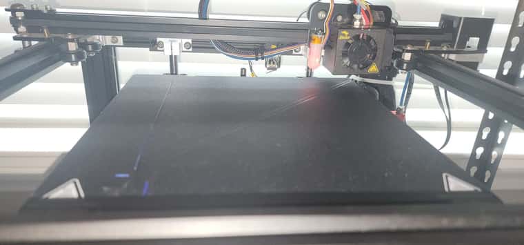
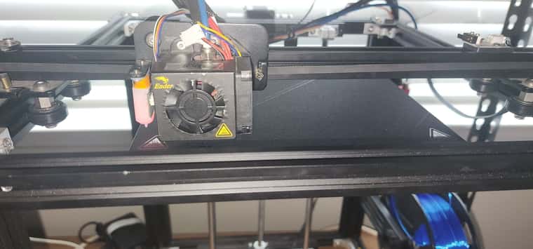
-
So did you understand the issue I mentioned regarding the probe X and Y offsets in your G31 being way too big?
Frederick
-
I accidentally put 1000 when playing with that. I changed it to 10 and it still goes to same place. Does not make a difference what i change it to it always goes to same place. See below for example
; Z-Probe
M950 S0 C"io7.out" ; create servo pin 0 for BLTouch
M558 P9 C"io7.in" H5 F120 T12000 ; set Z probe type to bltouch and the dive height + speedsG31 P500 X10 Y10 Z4.05 ; set Z probe trigger value, offset and trigger height G31 P500 X0 Y0 Z3.75
M557 X15:180 Y15:180 S20 ; define mesh grid M557 X15:215 Y15:195 S20 -
latest setting no change in homing
; Configuration file for Duet 3 MB 6HC (firmware version 3.3) ; executed by the firmware on start-up ; ; generated by RepRapFirmware Configuration Tool v3.3.16 on Thu Nov 16 2023 14:37:40 GMT-0600 (Central Standard Time) ; General preferences G90 ; send absolute coordinates... M83 ; ...but relative extruder moves M550 P"Ender 5 Pro" ; set printer name M918 P1 E4 F2000000 ; configure direct-connect display ; Network M552 P192.168.1.87 S1 ; enable network and acquire dynamic address via DHCP M586 P0 S1 ; enable HTTP M586 P1 S1 ; disable FTP M586 P2 S1 ; disable Telnet ; Drives M569 P0.0 S0 ; physical drive 0.0 goes backwards M569 P0.1 S0 ; physical drive 0.1 goes backwards M569 P0.2 S0 ; physical drive 0.2 goes forwards M569 P0.3 S0 ; physical drive 0.3 goes backwards M584 X0.0 Y0.1 Z0.2 E0.3 ; set drive mapping M350 X16 Y16 Z16 E16 I1 ; configure microstepping with interpolation M92 X80.00 Y80.00 Z400.00 E93.00 ; set steps per mm M566 X1200.00 Y1200.00 Z24.00 E300.00 ; set maximum instantaneous speed changes (mm/min) M203 X9000.00 Y9000.00 Z180.00 E6000.00 ; set maximum speeds (mm/min) M201 X500.00 Y500.00 Z100.00 E5000.00 ; set accelerations (mm/s^2) M906 X800 Y800 Z800 E1000 I50 ; set motor currents (mA) and motor idle factor in per cent M84 S30 ; Set idle timeout ; Axis Limits M208 X0 Y0 Z0 S1 ; set axis minima M208 X200 Y220 Z300 S0 ; set axis maxima ; Endstops M574 X2 S1 P"io0.in" ; configure switch-type (e.g. microswitch) endstop for high end on X via pin io0.in M574 Y2 S1 P"io1.in" ; configure switch-type (e.g. microswitch) endstop for high end on Y via pin io1.in M574 Z2 S2 ; configure Z-probe endstop for high end on Z ; Z-Probe M950 S0 C"io7.out" ; create servo pin 0 for BLTouch M558 P9 C"io7.in" H5 F120 T12000 ; set Z probe type to bltouch and the dive height + speeds G31 P500 X10 Y10 Z4.05 ; set Z probe trigger value, offset and trigger height G31 P500 X0 Y0 Z3.75 M557 X15:180 Y15:180 S20 ; define mesh grid M557 X15:215 Y15:195 S20 ; Heaters M308 S0 P"temp0" Y"thermistor" T100000 B4092 ; configure sensor 0 as thermistor on pin temp0 M950 H0 C"out0" T0 ; create bed heater output on out0 and map it to sensor 0 M307 H0 R0.532 K0.167:0.000 D13.56 E1.35 S1.00 B0 ; enable bang-bang mode for the bed heater and set PWM limit M140 H0 ; map heated bed to heater 0 M143 H0 S150 ; set temperature limit for heater 0 to 150C M308 S1 P"temp1" Y"thermistor" T100000 B4092 ; configure sensor 1 as thermistor on pin temp1 M950 H1 C"out1" T1 ; create nozzle heater output on out1 and map it to sensor 1 M307 H1 B0 S1.00 ; disable bang-bang mode for heater and set PWM limit M143 H1 S275 ; set temperature limit for heater 1 to 275C ; Fans M950 F0 C"out7" Q500 ; create fan 0 on pin out7 and set its frequency M106 P0 S0 H-1 ; set fan 0 value. Thermostatic control is turned off M950 F1 C"out8" Q500 ; create fan 1 on pin out8 and set its frequency M106 P1 S1 H1 T45 ; set fan 1 value. Thermostatic control is turned on M950 F2 C"out9" Q500 ; create fan 2 on pin out9 and set its frequency M106 P2 S1 H1:0 T45 ; set fan 2 value. Thermostatic control is turned on ; Tools M563 P0 S"Nozzle-0" D0 H1 F0 ; define tool 0 G10 P0 X0 Y0 Z0 ; set tool 0 axis offsets G10 P0 R0 S0 ; set initial tool 0 active and standby temperatures to 0C T0 ; ensures a tool is selected upon start up (allowing extrusion/retraction) ; Custom settings are not defined ; Miscellaneous M911 S10 R11 P"M913 X0 Y0 G91 M83 G1 Z3 E-5 F1000" ; set voltage thresholds and actions to run on power lossNothing i change on these g1 commands homeall.g makes a difference as well. I also tried to add the M208 X-150:150 Y-100:100 to this and no change! Always goes to same spot!
; homeall.g ; called to home all axes ; ; generated by RepRapFirmware Configuration Tool v3.3.16 on Thu Nov 16 2023 14:37:41 GMT-0600 (Central Standard Time) G91 ; relative positioning G1 H2 Z5 F6000 ; lift Z relative to current position G1 H1 X225 Y225 F3000 ; move quickly to X and Y axis endstops and stop there (first pass) G1 H2 X-5 Y-5 F6000 ; go back a few mm G1 H1 X200 Y225 F240 ; move slowly to X and Y axis endstops once more (second pass) G90 ; absolute positioning G1 X20 Y20 F6000 ; go to first bed probe point and home Z G1 X20 Y20 F6000 G30 ; home Z by probing the bed -
Looking at the image you posted it does not appear as if the probe offsets of X10 and Y10 are correct.
It looks like your probe is to the left of the nozzle and possibly slightly in front?
Have you tried to measure the offsets so you can use the correct values?
Regards homing:
Have you verified that simple G1 commands move the nozzle where they should and by the correct amount?
To get a printer working it is best to go step-by-step verifying each element before trying things like homing or creating a height map. There can be many simple configuration/wiring issues that can cause motion problems.
Frederick
-
The G1 commands move the nozzle up and down with no problem!! I used the bed calibration and set it at 4.05. All in the green! Used the g92 z0 and g30 s-1 to set Hight no issues.
G1 x10 and y10 I just did this as a test. i have tried x and Y 100, 120, -100 nothing makes a differance. Always same spot. Somthing is over writing the commands making them usless. I ran the RRF many times no change when i add the bl touch as endstop. Without it homes correctly. Something is telling the bl touch to go to the far end and not the same spot as x and y go to.
FYI The g32 command works on probing the bed. So assume the probe is working. Its shows the highs and lows i set the bed map at 180 x 180.
I am stumpt?
I assume everything works becuse without the bl touch as endstop it homes to the correct spot, the motors all go up and down correctly, the heat and thermistors all work.
Its just the BL touch homing position i cant get to change.As a stupid test if i tell the bed its only 110 x110 in size it will go to the middle of the bed. But thats still the edge of the home not the center. Its just looks like its there. dont know what else to try.
-
@ecnsupplies said in Homing issues with BL touch When I home!:
I just did this as a test. i have tried 100, 120, -100 nothing makes a differance.
What do you mean you have tried 100, 120, -100? Tried those values where or how?
I ran the RRF many times no change when i add the bl touch as endstop.
The problem I see with the RRF is it keeps folks like you from learning the commands, what they do and how to configure things.
I have never used the RRF. I started with my first printer by looking at a simple, sample config.g file and reading the on-line GCODE documentation.
The g32 command works on probing the bed.
I guess you are still using bed.g wrong and have it doing things related to Mesh Bed Compensation.
Have you verified, by jogging that X and Y axes on the DWC, that things go where they should by the correct amounts?
Please most your most recent homing files.
Thanks.
Frederick
-
@fcwilt said in Homing issues with BL touch When I home!:
I just did this as a test. i have tried 100, 120, -100 nothing makes a differance.
What do you mean you have tried 100, 120, -100? Tried those values where or how?
The G31 P500 X10 Y10 Z4.05 tried 100, 120, -100 and more. No change at all. ; set Z probe trigger value, offset and trigger height G31 P500 X0 Y0 Z3.75
**
I ran the RRF many times no change when i add the bl touch as endstop.The problem I see with the RRF is it keeps folks like you from learning the commands, what they do and how to configure things.
I have never used the RRF. I started with my first printer by looking at a simple, sample config.g file and reading the on-line GCODE documentation.
Tried the configurator because i was at a loss on what else to try!The g32 command works on probing the bed.
I guess you are still using bed.g wrong and have it doing things related to Mesh Bed Compensation.
Not sure what you mean on this? I set the bed calibration at 180 x 180 it probes the bed fine using G32 command. No issues.Have you verified, by jogging that X and Y axes on the DWC, that things go where they should by the correct amounts?
WHEN I JOG IT IS USING THE Z AXIS AS THE HOME BEGINING SPOT. It should be the side where the x and y home in the first pass. This will case an issue i am sure. But the distance part work. Just the starting is on the wrong side of the bed!! See picture of where it start as home and jogging should be opposite side of bed,Please most your most recent homing files.
Not sure where they are on the duet 3 will look for them and send asap.
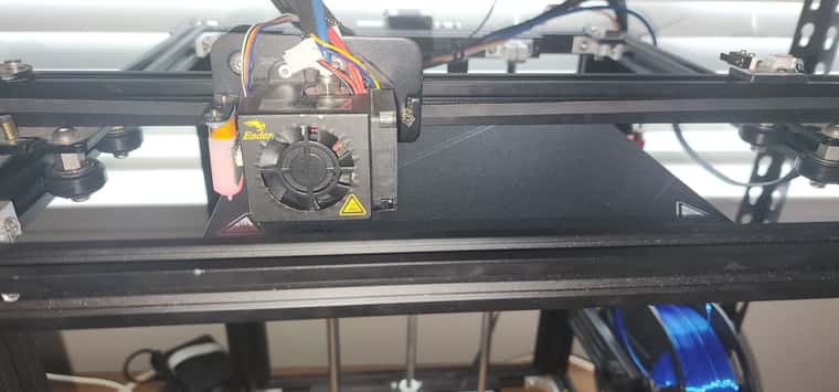
-
@fcwilt
Pics of Jogging. It thinks home is wrong side but does jog.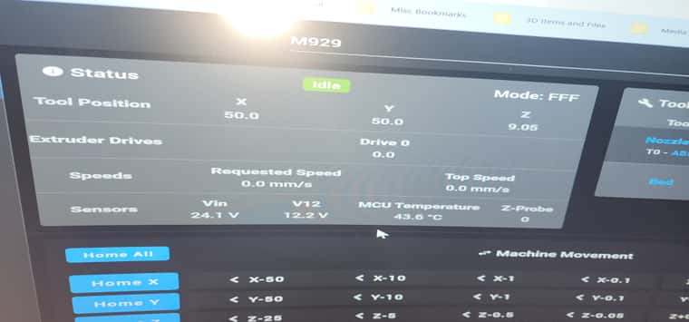 ![Home and Jogging 50.jpg]
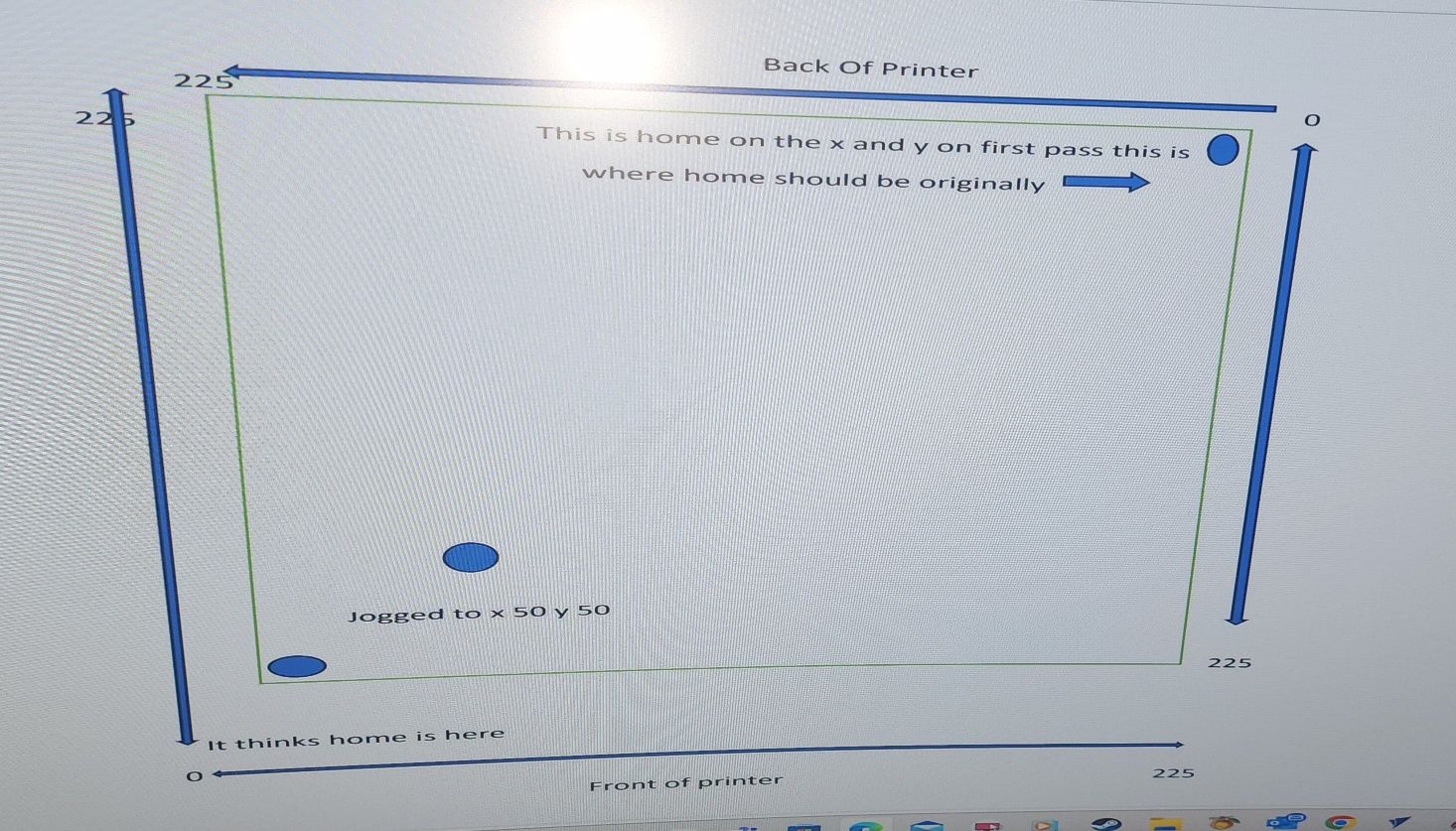
-
Why do you think home should be in the back right corner?
What does the word "home" mean to you?
Your printer appears to be moving correctly on X and Y.
Frederick
-
@fcwilt
When it was originally setup by the RRF configurator as a ender 3 and also when it was made from ender they called this home so i am as well. . When i take out the BL touch as endstop it reverts this back corner as home. When i put the bl touch back in as the endstop it flips it to the other side or as i call the front side of printer as home.
When i click on homing it moves to the back corner on the x and y part of homing ( first stage) then goes to the other side or front corner to home the z or probe. Hope this makes since. -
Yes when you home X or Y it moves to the max end of the axes, because you have the endstops at the max end of the axis.
But you have the min/max values of the axes such that 0,0 is in the left-front corner and 200,220 is the back-right corner.
In the homeALL.g file you have a G1 X20 Y20 command just before the G30. That is going to move near the left-front corner.
I think you are confusing "home" which is where the endstops are and "origin" which is where 0,0 is.
They can be the same or the can be different, there is no fixed relationship.
Frederick
-
@fcwilt
Under stood. Thank you for helping me to get the terminology correct. Understand the peaceable just not the language.***I changed the G1 X20 Y20 to G1 X110 Y110
IT HOMED TO THE MIDDLE OF BED> thank you.
Will test g32 command and a test cube next.
Much appreciated*** -
Re-visiting G32 and G29:
Recall that G32 is intended to be used with Bed Leveling (either Auto or Manual) and it runs bed.g which should contain the code needed to do the leveling.
Recall that G29 is intended to be used as part of Mesh Bed Compensation and it runs mesh.g which should contain the code needed to probe the bed and create the height map.
You are currently using G32 to run bed.g but your bed.g contains the code that should be in mesh.g.
So move your code from bed.g to mesh.g (creating mesh.g as needed) and then use G29 instead of G32 to probe the bed and create the height map.
Frederick
-
Your recommendation In the homeALL.g file you have a G1 X20 Y20 command just before the G30. That is going to move near the left-front corner fixed the homing issue. Changed it from G1 X20 Y20 to G1 X110 Y110.,
-
Still have one issue that hopefully you can tell me really quick without me doing trial and error by stopping and starting print jobs to get the job to start print at the center where it homes instead of the front corner edge. FYI. I told cura my slicer to print in center! Is this a duet issue or cura?
I found this! Will it work?
Put g28 in your config.g file, or you can put it in the start.g file or you can leave it out (the latter will require you to manually home before printing) either start.g or your slicer -
On the bed calibration
You want be to make a new file mesh.g and copy all files from bed.g to it!
; bed.g
; called to perform automatic bed compensation via G32
; generated by RepRapFirmware Configuration Tool v3.3.16 on Thu Nov 16 2023 14:37:40 GMT-0600 (Central Standard Time)
M561 ; clear any bed transform
G29 ; probe the bed and enable compensation
Copy all these files to mesh.g
; bed.g
; called to perform automatic bed compensation via G32
;
; generated by RepRapFirmware Configuration Tool v3.3.16 on Thu Nov 16 2023 14:37:40 GMT-0600 (Central Standard Time)
M561 ; clear any bed transform
G29  ; probe the bed and enable compensation
Should I put ; on all the bed.g files or delete the file?This is it.
Thank you for all you do!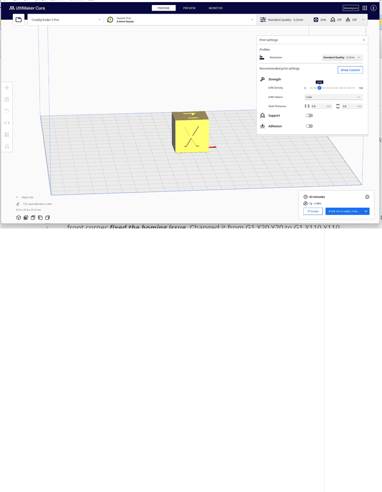
-
-
Regards bed.g versus mesh.g:
One of the reasons I suggest folks not depend on the RRF config tool is that it doesn't generate very good code.
It seems that the tool is behind the times and is not aware that G32 is not intended to be used for Mesh Bed Compensation.
Unless you intend to enable True Bed Leveling (either automatic or manual) bed.g should be empty or perhaps contain just a M291 command to put up a dialog stating that bed.g is mostly empty.

Regards starting a print at the center of the bed:
You may recall that I set the X and Y axes min/max, via M208, to put 0,0 at the center of the bed. I have never had an issue getting prints to start in the center with any of the slicers I have (and I have most of them). You do have to tell the slicer (just one time) about your printer and the size of the bed and the location of 0,0.
Regards G28 in your config.g file:
NOT a good idea. You don't want any part of your printer to start moving or heating or anything just when you power it on.
After I power up my printers I manually home them just to get a sense that all is fine and there are no disturbing noises being made.
Glad to help when I can. Feel free to ask why I do or suggest something. I like my approach to these things but everyone is unique and has their own likes and dislikes.
Frederick