Bed calibration error on g28 when using bl touch probe
-
Never mind i found the issue. Sorry
-
-
@fcwilt
I thought I had it figure out BUT NOT! I added the G30 as you requested as well to config.g and homeall.g? See below config.g and homeall.g files.
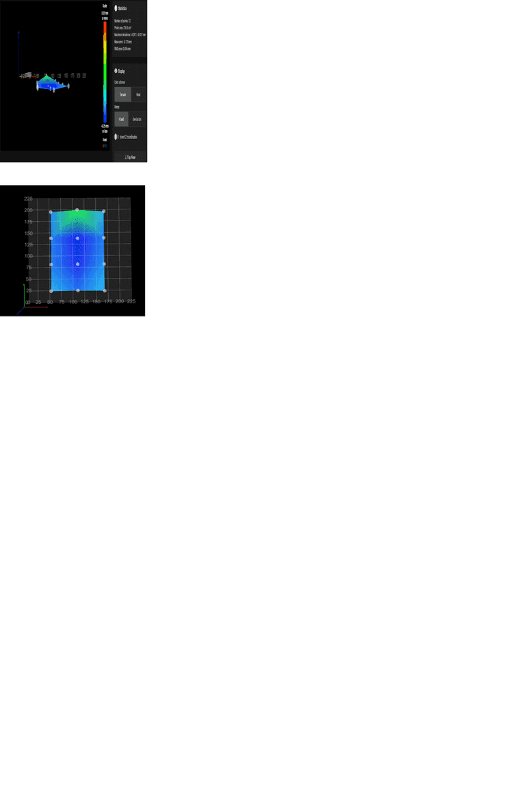
My problem is when I use the G29 command the bed on the chart shows below the 0 line, and gives this warning.Warning: the height map has a substantial Z offset. Suggest use Z-probe to establish Z=0 datum, then re-probe the mesh. 12 points probed, min error -0.257, max error -0.027, mean -0.179, deviation 0.054 Height map saved to file 0:/sys/heightmap.csvI ran the G92 ZO AND G30 S-1 to set and get the 0 height, It was 3.010 I added to the config.g under the
G31 ie: G31 X110 Y110 Z3.010
Every time I run the g29 to level the bed I get this warning and when I look at the chart its below the line and blue. I tried to manually change the bed height manually and also in the config.g it does not change it. Any ideas?RepRapFirmware height map file v2 generated at 2023-11-21 11:15, min error -0.257, max error -0.027, mean -0.179, deviation 0.054 axis0,axis1,min0,max0,min1,max1,radius,spacing0,spacing1,num0,num1 X,Y,50.00,200.00,20.00,200.00,-1.00,60.00,60.00,3,4 -0.161, -0.201, -0.155 -0.194, -0.240, -0.181 -0.194, -0.257, -0.194 -0.185, -0.027, -0.160
; Configuration file for Duet 3 MB 6HC (firmware version 3.3) ; executed by the firmware on start-up ; ; generated by RepRapFirmware Configuration Tool v3.3.16 on Thu Nov 16 2023 14:37:40 GMT-0600 (Central Standard Time) ; General preferences G90 ; send absolute coordinates... M83 ; ...but relative extruder moves M550 P"Ender 5 Pro" ; set printer name M918 P1 E4 F2000000 ; configure direct-connect display ; Network M552 P192.168.1.87 S1 ; enable network and acquire dynamic address via DHCP M586 P0 S1 ; enable HTTP M586 P1 S1 ; disable FTP M586 P2 S1 ; disable Telnet ; Drives M569 P0.0 S0 ; physical drive 0.0 goes backwards M569 P0.1 S0 ; physical drive 0.1 goes backwards M569 P0.2 S0 ; physical drive 0.2 goes forwards M569 P0.3 S0 ; physical drive 0.3 goes backwards M584 X0.0 Y0.1 Z0.2 E0.3 ; set drive mapping M350 X16 Y16 Z16 E16 I1 ; configure microstepping with interpolation M92 X80.00 Y80.00 Z800.00 E93.00 ; set steps per mm M566 X1200.00 Y1200.00 Z24.00 E300.00 ; set maximum instantaneous speed changes (mm/min) M203 X9000.00 Y9000.00 Z180.00 E6000.00 ; set maximum speeds (mm/min) M201 X500.00 Y500.00 Z100.00 E5000.00 ; set accelerations (mm/s^2) M906 X800 Y800 Z800 E1000 I50 ; set motor currents (mA) and motor idle factor in per cent M84 S30 ; Set idle timeout ; Axis Limits M208 X0 Y0 Z0 S1 ; set axis minima M208 X225 Y225 Z300 S0 ; set axis maxima ; Endstops M574 X2 S1 P"io0.in" ; configure switch-type (e.g. microswitch) endstop for high end on X via pin io0.in M574 Y2 S1 P"io1.in" ; configure switch-type (e.g. microswitch) endstop for high end on Y via pin io1.in M574 Z2 S2 ; configure Z-probe endstop for high end on Z ; Z-Probe M950 S0 C"io7.out" ; create servo pin 0 for BLTouch M558 P9 C"io7.in" H5 F120 T12000 ; set Z probe type to bltouch and the dive height + speeds G31 P500 X10 Y10 Z1.944 ; set Z probe trigger value, offset and trigger height G31 P500 X0 Y0 Z3.75 M557 X50:220 Y20:220 S20 ; define mesh grid M557 X15:215 Y15:195 S20 ; Heaters M308 S0 P"temp0" Y"thermistor" T100000 B4092 ; configure sensor 0 as thermistor on pin temp0 M950 H0 C"out0" T0 ; create bed heater output on out0 and map it to sensor 0 M307 H0 R0.532 K0.167:0.000 D13.56 E1.35 S1.00 B0 ; enable bang-bang mode for the bed heater and set PWM limit M140 H0 ; map heated bed to heater 0 M143 H0 S150 ; set temperature limit for heater 0 to 150C M308 S1 P"temp1" Y"thermistor" T100000 B4092 ; configure sensor 1 as thermistor on pin temp1 M950 H1 C"out1" T1 ; create nozzle heater output on out1 and map it to sensor 1 M307 H1 B0 S1.00 ; disable bang-bang mode for heater and set PWM limit M143 H1 S275 ; set temperature limit for heater 1 to 275C ; Fans M950 F0 C"out7" Q500 ; create fan 0 on pin out7 and set its frequency M106 P0 S0 H-1 ; set fan 0 value. Thermostatic control is turned off M950 F1 C"out8" Q500 ; create fan 1 on pin out8 and set its frequency M106 P1 S1 H1 T45 ; set fan 1 value. Thermostatic control is turned on M950 F2 C"out9" Q500 ; create fan 2 on pin out9 and set its frequency M106 P2 S1 H1:0 T45 ; set fan 2 value. Thermostatic control is turned on ; Tools M563 P0 S"Nozzle-0" D0 H1 F0 ; define tool 0 G10 P0 X0 Y0 Z0 ; set tool 0 axis offsets G10 P0 R0 S0 ; set initial tool 0 active and standby temperatures to 0C T0 ; ensures a tool is selected upon start up (allowing extrusion/retraction) ; Custom settings are not defined ; Miscellaneous M911 S10 R11 P"M913 X0 Y0 G91 M83 G1 Z3 E-5 F1000" ; set voltage thresholds and actions to run on power loss ; homeall.g ; called to home all axes ; ; generated by RepRapFirmware Configuration Tool v3.3.16 on Thu Nov 16 2023 14:37:41 GMT-0600 (Central Standard Time) G91 ; relative positioning G1 H2 Z5 F6000 ; lift Z relative to current position G1 H1 X225 Y225 F3000 ; move quickly to X and Y axis endstops and stop there (first pass) G1 H2 X-5 Y-5 F6000 ; go back a few mm G1 H1 X225 Y225 F240 ; move slowly to X and Y axis endstops once more (second pass) G90 ; absolute positioning G1 X110 Y110 F6000 ; go to first bed probe point and home Z G1 X20 Y20 F6000 G30 X110 Y110 Z0 ; home Z by probing the bed ; Uncomment the following lines to lift Z after probing ;G91 ; relative positioning ;G1 Z5 F200 ; lift Z relative to current position ;G90 ; absolute positioning ; homez.g ; called to home the Z axis ; ; generated by RepRapFirmware Configuration Tool v3.3.16 on Thu Nov 16 2023 14:37:41 GMT-0600 (Central Standard Time) G91 ; relative positioning G1 H2 Z5 F6000 ; lift Z relative to current position G90 ; absolute positioning G1 X-5 Y15 F3000 ; go to first probe point G30 X110 Y110 Z0 ; home Z by probing the bed ; Uncomment the following lines to lift Z after probing ;G91 ; relative positioning ;G3 Z5 F200 ; lift Z relative to current position ;G90 ; absolute positioning ; bed.g ; called to perform automatic bed compensation via G32 ; ; generated by RepRapFirmware Configuration Tool v3.3.16 on Thu Nov 16 2023 14:37:40 GMT-0600 (Central Standard Time) M561 ; clear any bed transform G29 ; probe the bed and enable compensation -
Hi
Why do you have any parameters after the G30 commands?
Just move to bed center and do a G30 all by itself.
When I mention the X and Y offsets I am talking about the G31 in your config.g file where the X and Y parameter specify the distance from the tip of the nozzle to the tip of the probe in both the X and Y directions.
You currently have them as X10 and Y10 and you haven't yet confirmed that your probe is actually 10mm to the right of the nozzle and 10mm to the rear of the nozzle.
If you haven't done so just measure the two distances and enter them into the G31 in your config.g file and reboot the machine.
Frederick
-
Did as you asked. Removed the g30 and measured the bl touch it was 40mm x and 5mm y Replaced the 10s to the new measurements in g31 line.
That only moved it over but not UP -
No fixing the G31 was not related to the original problem.
Have you created a new height map with the bed at printing temp and setting the Z=Datum using a G30 probing at bed center?
Frederick
-
@fcwilt said in Bed calibration error on g28 when using bl touch probe:
created a new height map
Please don't get flustered, i just don't know the terminology. Only way i know to create a new height map is to run the g29 in the compensation and calibration page on the duet dashboard.
First i run the g92 z0 to set the 0 head height then g30 s-1 to get the height that i put in the config.g G31 line.
I then open the compensation and calibration and run g29 to see that the bed plate design is below the 0 line. ALLMOST ALL BLUE.PS This all started when i changed the z motor steps from 400 to 800 because my height was off by 1/2
-
@fcwilt
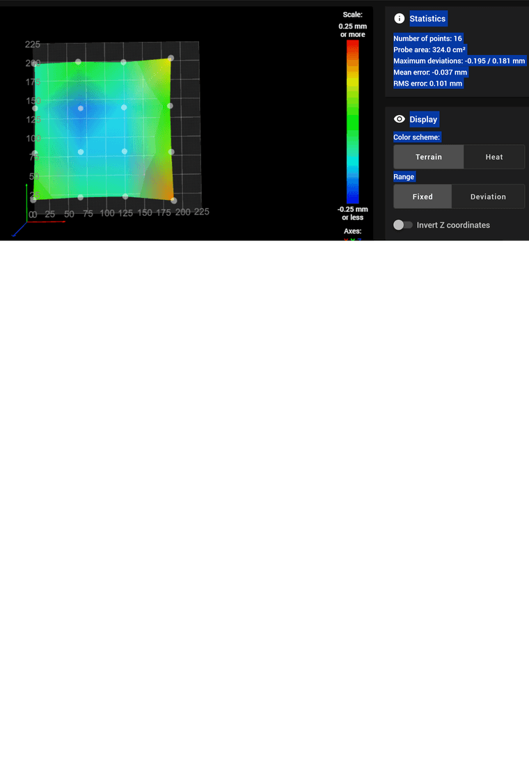
I think i have a brain Tumor. I clicked on invert z axis in the calibration page and it looks much better. Running the calibration again and hope this was all it was.
So sorry for not seeing that switch. -
Please don't get flustered, i just don't know the terminology.
All is good here.
First i run the g92 z0 to set the 0 head height then g30 s-1 to get the height that i put in the config.g G31 line.
Please elaborate on what you are doing. I don't understand as I have never done anything like that. I guess you are trying to determine the probe Z Trigger Height?
I then open the compensation and calibration and run g29 to see that the bed plate design is below the 0 line. ALLMOST ALL BLUE.
Please post your mesh.g file.
Thanks.
Frederick
-
@fcwilt
That was it. A little bowed in the middle but will get a glass plate or replace hotend bar.
Thank you again for all your help.
-