Toolboard 1LC v1.3 wiring
-
@Arminas yes, just a blob of solder over those 2 pads.
You only need to connect 1 pair of CAN wires to the CAN connector.
We recommend you use a 5A fuse in the +VIN power wire.
See tab "Connecting WITHOUT Duet 3 Tool Distribution Board" at https://docs.duet3d.com/Duet3D_hardware/Duet_3_family/Duet_3_Toolboard_1LC
Duet WiFi hardware designer and firmware engineer
Please do not ask me for Duet support via PM or email, use the forum
http://www.escher3d.com, https://miscsolutions.wordpress.com -
@dc42 Thank you.
Yes, I have added a 5A fuse. Okay, so CAN wires are black and red that I need to use.
-
@Arminas you can use either pair because the two pairs are connected together on the tool board.
Duet WiFi hardware designer and firmware engineer
Please do not ask me for Duet support via PM or email, use the forum
http://www.escher3d.com, https://miscsolutions.wordpress.com -
@dc42 I am not sure if I understand it. So I can use only one wire for CAN and 2 wires for power?
-
@dc42 "4-wire fan output (also accepts a 2- or 3-wire fan) intended for use as the print cooling fan.
2A total max current for OUT1 and OUT2 when VIN selected (v1.1 board), 0.8A total max current for OUT1 and OUT2 on 12V.
This output is protected by a flyback diode.
Note On v1.0 boards and earlier, VOUT on OUT_1 and OUT_2 is set to 12V. On v1.1 boards, voltage is selectable between 12V and VIN, using VOUT for OUT_1, OUT_2 pins.
Note When using a 4-wire fan, the tacho reading is valid at all PWM settings."This means that both outputs have 0.8A in total or each have 0.8A? my fan is 1.2A, so I guess I just won't be able to use max power?
-
@Arminas said in Toolboard 1LC v1.3 wiring:
@dc42 I am not sure if I understand it. So I can use only one wire for CAN and 2 wires for power?
CAN bus uses a twisted pair of wires (2 wires). It uses a bus topology, so all devices are wired consecutively along the bus, twisted pair in and twisted pair out. The last device on the bus has twisted pair in, and then terminates the bus with a resistor.
As you only have a mainboard and 1LC, you only need two wires for CAN to go between them. I think you have a Duet 3 Mini 5+, so the wiring for CAN will look like this, but without the resistor:
(from https://docs.duet3d.com/Duet3D_hardware/Duet_3_family/Duet_3_Toolboard_1LC#can-connection-1)
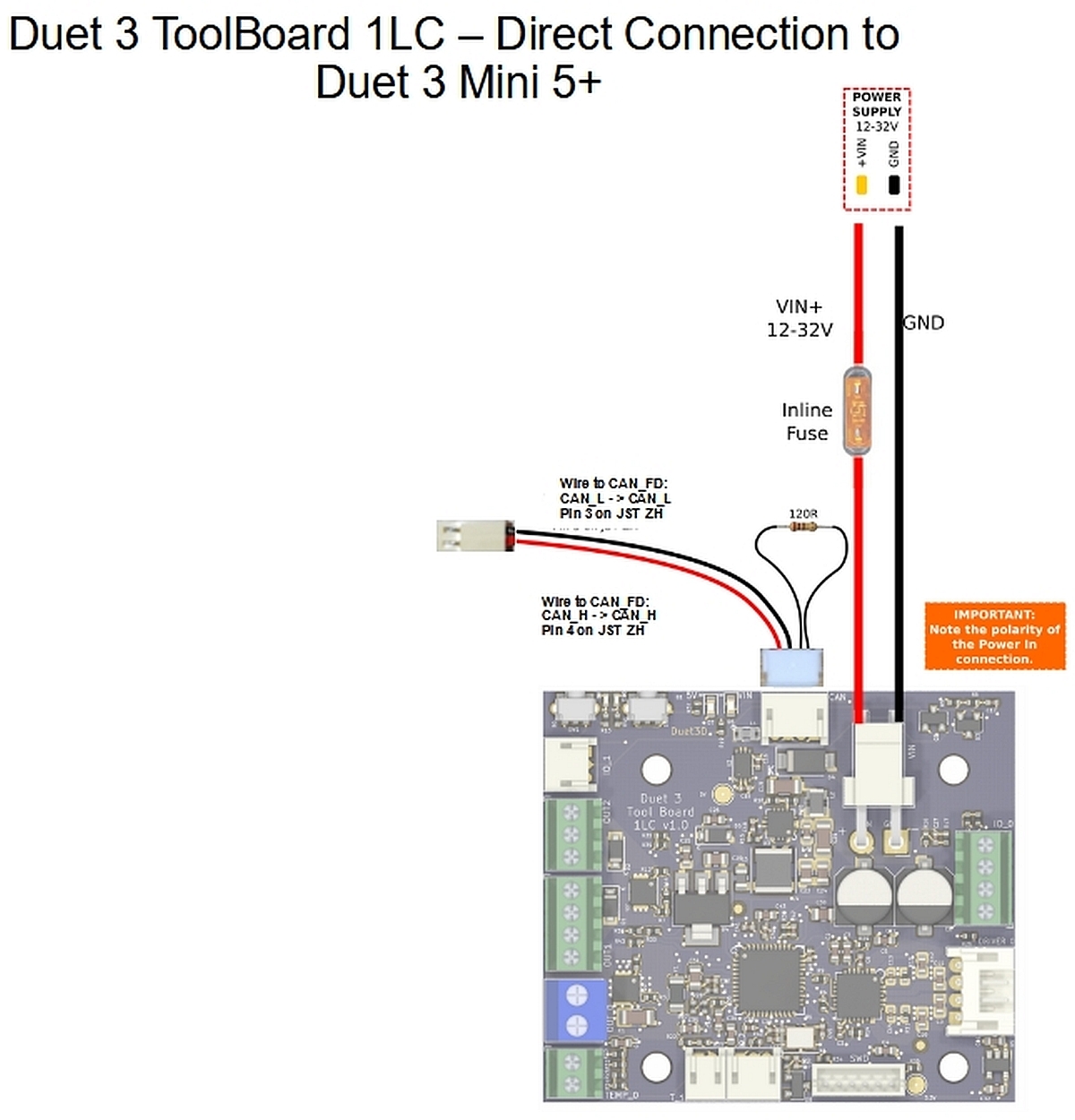
You can't use any left over CAN wires for power, they are too small to provide the current for heaters and stepper motors.
Ian
-
@Arminas said in Toolboard 1LC v1.3 wiring:
This means that both outputs have 0.8A in total or each have 0.8A? my fan is 1.2A, so I guess I just won't be able to use max power?
If you use the on-board 12V regulator, yes. You shouldn't use a 1.2A fan at all, because they use the most power when starting up, so you will burn out the 12V regulator, even if you set the fan to 50%. Better to get a 24V fan, and use VIN, then you are only limited by the connector, which is 2A on JST PH.
Ian
Bed-slinger - Mini5+ WiFi/1LC | RRP Fisher v1 - D2 WiFi | Polargraph - D2 WiFi | TronXY X5S - 6HC/Roto | CNC router - 6HC | Tractus3D T1250 - D2 Eth
-
@droftarts this 12V fan with 1.2A comes with stock RatRig printer. Is it okay to use it if it's plugged into the main board?
-
@Arminas No, it's the same current limit on a Duet 3 Mini 5+, see https://docs.duet3d.com/Duet3D_hardware/Duet_3_family/Duet_3_Mini_5+_Hardware_Overview#operating-limits
12V current limit - 800mA (only used for outputs OUT_3 thru OUT_6, when selected)
Also, that's maximum total current for all 12V devices, not 0.8A on each connector. I advise finding a similar 24V fan, assuming you are using a 24V PSU. You could run the toolboard on 12V, then the fan can run from VIN, but then so will the hot end and stepper motor.
Ian
Bed-slinger - Mini5+ WiFi/1LC | RRP Fisher v1 - D2 WiFi | Polargraph - D2 WiFi | TronXY X5S - 6HC/Roto | CNC router - 6HC | Tractus3D T1250 - D2 Eth
-
@droftarts After installing the 1LC toolboard, I can not extrude/retract extruder motor via DWC. Maybe you see what I did wrong in the config?
; General preferences
G90 ; send absolute coordinates...
M83 ; ...but relative extruder moves
M550 P"V-Core 3.1-1" ; set printer name
M669 K1 ; CoreXY
G21 ; Set Units to Millimeters
G4 S2 ; wait for expansion boards to start; Network
M552 S1 ; enable network and acquire dynamic address via DHCP
M586 P0 S1 ; enable HTTP
M586 P1 S0 ; disable FTP
M586 P2 S0 ; disable Telnet; Drives
M569 P0 S0 D3 ; physical Z1 drive 0 goes forwards
M569 P1 S0 D3 ; physical Z2 drive 1 goes forwards
M569 P2 S0 D3 ; physical Z3 drive 2 goes forwards
M569 P3 S1 D3 ; physical Y drive 3 goes backwards
M569 P4 S1 D3 ; physical X drive 4 goes backwards
M569 P121 S0 D3 ; physical E drive 121 goes forwards
M584 X4 Y3 Z0:1:2 E121 ; set drive mapping
M350 X16 Y16 Z16 E16 I1 ; configure microstepping with interpolationM92 X80.00 Y80.00 Z800.00 E415.00 ; set steps per mm
M906 X1700 Y1700 Z1700 E700 I30 ; set motor currents (mA) and motor idle factor in per cent
M84 S30 ; Set idle timeoutM205 X5.00 Y5.00 Z1.00 E60.00 P1 ; set maximum instantaneous speed changes (mm/s)
M203 X30000.00 Y30000.00 Z3600.00 E10800.00 ; set maximum speeds (mm/min)
M201 X6000.00 Y6000.00 Z100.00 E10000.00 ; set maximum accelerations (mm/s^2)
M204 P1000 T6000 ; set printing and travel acceleration; Axis Limits
M208 X0 Y0 Z-1 S1 ; set axis minima
M208 X415 Y405 Z410 S0 ; set axis maxima
M671 X0:203.5:408.7 Y0.5:409:0.5 S5 ; define positions of Z leadscrews or bed levelling screws
M556 S100 X0.27 Y0 Z0 ; axis skew compensation; Endstops
M574 X1 S1 P"121.io2.in" ; configure active low endstops
M574 Y2 S1 P"io0.in" ; configure active high endstops
M574 Z1 S2 ; configure Z-probe endstop for low end on Z; Heaters
M308 S0 P"temp0" Y"thermistor" T100000 B3950 A"Bed" ; configure sensor 0 as thermistor on pin temp0
M950 H0 C"out0" T0 Q500 ; create bed heater output on out0 and map it to sensor 0
M307 H0 R0.698 K0.390:0.000 D5.08 E1.35 S1.00 B0 ; disable bang-bang mode for the bed heater and set PWM limit
M140 H0 ; map heated bed to heater 0
M143 H0 S110 ; set temperature limit for heater 0 to 110C; Tools
M563 P0 D0 H1 F1 ; define tool 0
G10 P0 X0 Y0 Z0 ; set tool 0 axis offsets
G10 P0 R0 S0 ; set initial tool 0 active and standby temperatures to 0CM308 S1 P"121.temp0" Y"thermistor" T100000 B4725 C7.060000e-8 A"Hotend"
M950 H1 C"121.out0" T1 ; create nozzle heater output on out2 and map it to sensor 1
M307 H1 R1.774 K0.362:0.276 D6.68 E1.35 S1.00 B0 V23.9 ; disable bang-bang mode for heater and set PWM limit
M143 H1 S285 ; set the maximum temperature in C for heater; Fans
M950 F0 C"121.!out1+out1.tach" Q500 ; create fan 1 on pin out4 and set its frequency
M106 P0 C"Layer Fan" S0 H-1 ; set fan 1 name and value. Thermostatic control is turned offM950 F1 C"121.out2" Q500 ; create fan 0 on pin out3 and set its frequency
M106 P1 C"Hotend Fan" S1 H1 T45 ; set fan 0 name and value. Thermostatic control turned on for HotendM950 F2 C"out6" Q500 ; create fan 2 on pin out6 and set its frequency
M106 P2 C"Duet fan" S1 H-1 ; set fan 2 value. Thermostatic control is turned off; BLTouch
M950 S0 C"121.^io0.out" ; Create a servo pin on 121.io0
M558 P9 C"121.^io0.in" H5 F240 T10800 A5 ; set Z probe type to unmodulated and the dive height + speeds
G31 P25 X-30 Y-14.50 Z1.5 ; set Z probe trigger value, offset and trigger height, more Z means closer to the bed; Accelerometer LIS3DH and Input shaping
;M955 P0 I10 C"spi.cs2+spi.cs1"
M593 P"mzv" F45M404 N1.75 D0.6 ; Filament width and nozzle diameter
T0; Pressure Advance
M572 D0 S0.07 -
@Arminas said in Toolboard 1LC v1.3 wiring:
M569 P121 S0 D3 ; physical E drive 121 goes forwards
M584 X4 Y3 Z0:1:2 E121 ; set drive mappingYou need to set the 1LC driver number, ie 121.0, not just the CAN address:
M569 P121.0 S0 D3 ; physical E drive 121 goes forwards
M584 X4 Y3 Z0:1:2 E121.0 ; set drive mapping
Send
M98 P"config.g"in the console to check for any other errors.Ian
Bed-slinger - Mini5+ WiFi/1LC | RRP Fisher v1 - D2 WiFi | Polargraph - D2 WiFi | TronXY X5S - 6HC/Roto | CNC router - 6HC | Tractus3D T1250 - D2 Eth
-
This post is deleted! -
@droftarts I have one more question, but it's related to heaters and fans Q value:
"If using an SSR then set the "Q" parameter in the M950 command to a low frequency like 10 Hz." - what is the explanation of such a low Q parameter? In duet page it's also said to use 250Hz for fans and heaters. I took a standard RatRig config and fans there have a Q500.Just trying to understand and choose the optimal parameters, thank you.
-
@Arminas We choose default settings that are applicable to most situations. Check the datasheets for your SSR, fans and heaters if you feel they are incorrect for you.
An SSR can be switching mains voltage or a PSU. Every time it switches, it puts pressure on the supply, and the SSR will have a switching lifetime. Setting it higher will reduce the lifespan of the SSR and potentially the PSU.
Ian
Bed-slinger - Mini5+ WiFi/1LC | RRP Fisher v1 - D2 WiFi | Polargraph - D2 WiFi | TronXY X5S - 6HC/Roto | CNC router - 6HC | Tractus3D T1250 - D2 Eth
-
@droftarts "On-off time ≤ 10mS" - if this is the correct parameter of SSR to look at, it is 100 Hz. So Q should not be more than 100 Hz?
When my printer is heating the bed, lights in the room are flickering (Q was 10 Hz). So I tried to increase the Q parameter to default 500 Hz - flickering was gone, but bed temp was not stable. I thought I will find the sweet spot of Q where bed temperature is stable enough to not affect the print, but not too intense to make the light flicker.
-
@droftarts Also, Q parameter may affect the electricity consumption as well?
-
@dc42 what is the maximum air temperature for 1LC?
-
@Arminas said in Toolboard 1LC v1.3 wiring:
Is this the SSR you have? https://ratrig.com/electronics/power-supplies-ssrs/clin-ssr-40a-relay.html
The closest datasheet I can find for this SSR is here: http://www.clin.cn/product-detail.asp?id=62 (the part number matches)."On-off time ≤ 10mS" - if this is the correct parameter of SSR to look at, it is 100 Hz. So Q should not be more than 100 Hz?
That sounds correct, and 100Hz would be the absolute maximum switching rate it is capable of. At 500Hz, sometimes it is responding, other times not, which would lead to unstable switching and heating. I think half of 100Hz, ie 50Hz, would be the maximum I would want to set it to for longevity and to avoid it heating up. And even then, I think that would shorten it's life. Unfortunately the datasheet doesn't give any information on switching life or PWM rating. Caveat emptor, as they say.
Also, Q parameter may affect the electricity consumption as well?
How/why? I doubt it, unless there are significant power losses each time it switches. Or switching fast causes it to heat up. But then fast switching is likely going to put stress on the components of the PSU, too. I would tend to set the Q parameter as low as possible, to avoid the SSR heating up and because a bed doesn't need it to be very high as it is slow to heat and cool, but high enough that it doesn't audibly annoy you (they can click loudly) or cause other problems like flickering lights.
what is the maximum air temperature for 1LC?
This is something that we've been meaning to add to the documentation, but it is complicated. All Duet3D boards (other than the 23CL) have components only rated to 85C, so that is the absolute maximum, and doesn't take into account self-heating (mostly from stepper drivers, MOSFETs, etc). However, this can be offset if there is a fan or convective airflow to cool the board. Generally, we can use the on-board MCU temperature sensor to check it isn't significantly over-temperature, however the accuracy of these aren't great, and can be -11C to +6C out. Therefore, we are going to recommend an absolute maximum of 75C, as reported by the onboard MCU temperature sensor. But be aware that running close to that temperature is likely to shorten the life of the electronic components.
Ian
Bed-slinger - Mini5+ WiFi/1LC | RRP Fisher v1 - D2 WiFi | Polargraph - D2 WiFi | TronXY X5S - 6HC/Roto | CNC router - 6HC | Tractus3D T1250 - D2 Eth
-
@droftarts Okay, thanks. Regarding the max temp, I am planning to install the chamber heater, so I think I will have to add a small fan for the 1LC
-
@Arminas What temperature are you planning on heating the chamber to?
Ian
Bed-slinger - Mini5+ WiFi/1LC | RRP Fisher v1 - D2 WiFi | Polargraph - D2 WiFi | TronXY X5S - 6HC/Roto | CNC router - 6HC | Tractus3D T1250 - D2 Eth