Refurbishing 3d printer with Duet: pictures, gcode, etc.
-
In the following posts I will post details about the refurbisning process for my 3D printer. The goal is to help the ... somewhat beginners to deal with it, as even for me, with good background, it was a scarier experience, mainly because I did not had the needed time to dive into this, but I had an absolute need to make this printer work (or to throw it in a big garbage bin.
The printer was an enclosed 600x600x800, active heated, glass bed, dual head, DoWell DH8 printer.
It was as crappy as one can get, but not like the worst on the market, not by far. However, it was plagued by some stuff:- Crappy bearings and belts. Those I have not replaced yet, they are on the list.
- Poor acces to service and repair
- Zero acces to source code, wich was anyway incomplete, buggy but functioning... overall. Marlin flavour. Could not install on it a filament sensor (magnetic), or do any upgrades and tinkering. Support... 1 star from 10. Maybe 2 star, as they finally decided that this can be done, and offerend to sell me a BTT magnetic sensor at double the price, doubtfull functioning.
Believe or not, this was the second reason. - The first was when, some evening, the board seems to be locked. I asked them, and they said, oh, they locked on time interval, for maintenance. WTF?
- Cabinet heating. Now, that was some stuff. When printing PC, I needed to keep the door somewhat opened, but not too, as the cabinet fan was not a thermostatic fan, and the temperature could well exceed 75C, wich was bad for the printer, if not for the printed part.
- Good printing heads, but HEAVY, and not properly cooled. To change them, it would have not been easily possible, as either I needed to CNC my own cooling system or to change the extruder for a water cooling system. To print PETG in summer (hot summer, no AC), it was almost impossible, as the filament would be softened because poor cooling of the extruder and throat. Why not being easily possible to change the extruder? Because ZERO acces to source code.
- Do I need to say that at the first print, the hotend dropped on the part and triggered the bed collision system (wired in firmware with the filament over alarm, hehe...)
Good things:
- Mechanical basically done
- Wiring done
- PSU ok
- External drivers in place
- The system, overall, was relatively well thinked, but the implementation lacked (still lacking) quality and ... the simple stuff wich make life easier. As I said to them, it is a pity they did not do what they could have done. I tried to point to them the weak points, first being the hotend dropping onto the part due to vibrations.
This one was in fact an antologic event. I mean, the throat was completely round, and they tried to fix it with a M3 grub screw, overtightened. Guess what? It did not worked. How to explain to somebody notwilling to accept a mistake, that at least they could have used a pointed grub screw, and do that a ... M4, as the M3 was ... rounded from the factory.
And so on.
I still recommend such a construction. It will save a lot of work than start from scratch, but starting from scratch may have some advantages too. It is up to you. If you are able to start from scratch, for sure you do not need this topic at all.I will start to post some images and code from the next post.
This way I hope I will repay the help received from this forum, wich really, really helped me.
This is why I chosen Duet in fact, for support. And because there were not real competitors on the market for my kind of printer and needs.
Initially I wanted to buy a BTT with Klipper, but thinking about ... oriental support, and they not having boards really suited for big printers, high temperature, thermocouples, external drivers, etc, I gave up to that alternative, wich is viable anyway.Oh, and the most important: believe or not, God told me to choose Duet. He was right, I did the printer in no time... almost.
I am smiling now saying that, so you may take it like a joke, or like... my intuition, as you wish.
Right now, I think He would want me to ask from Duet team, to improve that filament sensor, but that may be only my personal wish
-
@soare0
First, config.g; Configuration file for Duet 3 MB 6XD (firmware version 3.3) ; executed by the firmware on start-up ; ; generated by RepRapFirmware Configuration Tool v3.4.0 on Wed Dec 20 2023 17:08:51 GMT+0200 (Eastern European Standard Time) ; General preferences M575 P1 S1 B57600 ; enable support for PanelDue G90 ; send absolute coordinates... M83 ; ...but relative extruder moves M550 P"xxxxxxxxxx" ; set printer name ; Wait a moment for the CAN expansion boards to start G4 S2 ; Network M551 P"xxxxxxxxxxx" ; set password M552 Pxxx.xxx.x.xxx S1 ; enable network and set IP address M553 P255.255.255.0 ; set netmask M554 P192.168.1.1 ; set gateway M586 P0 S1 ; enable HTTP M586 P1 S0 ; disable FTP M586 P2 S0 ; disable Telnet ; Drives M569 P0.0 R0 S0 T5:5:10:0 ; X drive 0.0 goes forwards M569 P0.1 R0 S1 T5:5:10:0 ; Y drive 0.1 goes backwards M569 P0.2 R0 S1 T5:5:10:0 ; Z0 drive 0.2 goes backwards M569 P0.3 R0 S1 T5:5:10:0 ; Z1 drive 0.3 goes backwards M569 P0.4 R0 S1 T5:5:10:0 ; Z2 drive 0.4 goes backwards M569 P0.5 R0 S1 T5:5:10:0 ; Z3 drive 0.5 goes backwards M569 P1.0 R0 S0 T5:5:10:0 ; extruder drive 1.0 goes forwards M584 X0.0 Y0.1 Z0.2:0.3:0.4:0.5 E1.0 ; set drive mapping M671 X-70:-70:670:670 Y70:530:530:70 S0.5 ; POSITION OF LEADSCREW FRONT LEFT, RL, RR, FR M208 X0:524 Y0:600 ; Xcarriage move, Ycarriage move M92 X80.00 Y160.00 Z2400.00 E932 ; set steps per mm M566 X900.00 Y900.00 Z60.00 E120.00 ; set maximum instantaneous speed changes (mm/min) M203 X6000.00 Y6000.00 Z180.00 E1200.00 ; set maximum speeds (mm/min) M201 X500.00 Y500.00 Z20.00 E250.00 ; set accelerations (mm/s^2) M906 X3000 Y3000 Z3000 E1500 I30 ; set motor currents (mA) and motor idle factor in per cent M84 S30 ; Set idle timeout ; Axis Limits M208 X0 Y0 Z0 S1 ; set axis minima M208 X525 Y601 Z800 S0 ; set axis maxima ; Endstops M574 X1 S1 P"io1.in" ; configure switch-type (e.g. microswitch) endstop for low end on X via pin io1.in M574 Y1 S1 P"io2.in" ; configure switch-type (e.g. microswitch) endstop for low end on Y via pin io2.in M574 Z1 S2 ; configure Z-probe endstop for low end on Z ; Z-Probe M950 S0 C"io7.out" ; create servo pin 0 for BLTouch M558 P9 C"io7.in" H5 F120 T6000 ; set Z probe type to bltouch and the dive height + speeds G31 P500 X0 Y0 Z2.5 ; set Z probe trigger value, offset and trigger height M557 X20:520 Y50:550 S50 ; define mesh grid ; Heaters M308 S0 P"temp0" Y"thermistor" T100000 B4138 ; configure sensor 0 as thermistor on pin temp0 M950 H0 C"out0" T0 ; create bed heater output on out0 and map it to sensor 0 M307 H0 B1 S1.00 ; enable bang-bang mode for the bed heater and set PWM limit M140 H0 ; map heated bed to heater 0 M143 H0 S150 ; set temperature limit for heater 0 to 150C M308 S1 P"1.spi.cs1" Y"thermocouple-max31856" ; configure sensor 1 as thermocouple via CS pin 1.spi.cs0 M950 H1 C"1.out0" T1 ; create nozzle heater output on 1.out0 and map it to sensor 1 M307 H1 B0 S1.00 ; disable bang-bang mode for heater and set PWM limit M143 H1 S400 ; set temperature limit for heater 1 to 400C M308 S2 P"temp1" Y"pt1000" ; configure sensor 2 as pt1000 via temp1 M950 H2 C"out8" T2 ; create main chamber heater output on out8 and map it to sensor 2 M307 H2 B1 S1.00 ; enable bang-bang mode for heater and set PWM limit M141 P0 H2 ; map chamber0 to heater 2 M143 H2 S80 ; set temperature limit for heater 2 to 80C M308 S3 P"1.temp2" Y"pt1000" A"Apa_E0" ; configure sensor 3 as pt1000 via 1.temp2 M308 S4 P"1.temp1" Y"thermistor" A"Fil_CH" ; configure sensor 4 as thermistor via 1.temp1 M950 H4 C"1.out1" T4 ; create filament heater output on 1.out7 and map it to sensor 4 M307 H4 B1 S1.00 ; enable bang-bang mode for heater and set PWM limit M141 P1 H4 ; map chamber1 to heater 4 M143 H4 S100 ; set temperature limit for heater 1 to 100C ; Fans M950 F0 C"!1.out3+out3.tach" Q500 ; create fan 0 on pin 1.out3 and set its frequency. Part cooling fan M106 P0 S1 C"Aer_E0" H-1 ; set fan 0 value. Thermostatic control is turned off M950 F1 C"1.out6" Q500 ; create fan 1 on out6 and set its frequency M106 P1 S1 H1 T45 ; set fan 1 value. Thermostatic control senzor 1 is turned on. water circuit pupm M950 F2 C"out7" Q500 ; create fan 2 on out7 and set its frequency M106 P2 S1 C"Camera" H2 T65 ; set fan 2 value. Thermostatic control senzor 2 is turned on. Main chamber exhaust fan ;heaters fault detection M570 H2 P9999 T60 M570 H1 P9999 T90 M570 H0 P9999 T150 M570 H4 P9999 T100 ; Tools M563 P0 S"E0" D0 H1 F0 ; define tool 0 G10 P0 X0 Y0 Z0 ; set tool 0 axis offsets G10 P0 R0 S0 ; set initial tool 0 active and standby temperatures to 0C ; Filament sensors ;M591 P1 C"1.io0.in" S1 D0 ; define simple microsw fil sensor at bd 1 inp 0, low is fil runout ;M591 D0 P3 C"1.io1.in" S1 ; filament monitor magnetic duet M591 D0 P7 C"1.io1.in" S1 R20:200 E10 L1.246 A0 ; filament magnetic monitor Orthus. ;Triggere - senzori de filament si de pat M950 J6 C"1.io0.in" ;define pin GPIO 6 1.io0.in M581 T2 P6 S0 R0 ; define trigger T2, pause on filament left over, comutarea pe active /inactive edge pin GPIO 6, anytime M950 J7 C"1.io3.in" ;define pin GPIO 7 1.io3.in M581 T3 P7 S0 R0 ; define trigger T3, pause on filament right over, comutarea pe active /inactive edge pin GPIO 7, anytime M950 J8 C"1.io4.in" ;define pin GPIO 8 1.io4.in M581 T4 P8 S0 R0 ; define trigger T4, pause on bad filament diameter, comutarea pe active /inactive edge pin GPIO 8, anytime ;M950 J9 C"1.io3.in" ;define pin GPIO 9 1.io3.in ;M581 T4 P9 S0 R0 ; define trigger T5, pause on bed touch, comutarea pe active /inactive edge pin GPIO 9, anytime ; Miscellaneous stuff global decalibrache = 0 ; set a global variable used in selecting pause types (normal pause, filament errors, bed touch) M501 ; load saved parameters from non-volatile memory M911 S20 R22 P"M913 X0 Y0 G91 M83 G1 Z3 E-1 F1000" ; set voltage thresholds and actions to run on power loss T0 ;select first tool - commentedI will comment the sections in the next posts.
The first iteration was done with the configuration software, wich did a great job, making a generic, albeit not funtional set of files. With it I could learn about pinout, capabilities and stuff. However, it rarely can be let as it is, but hey, it reduce the learning process difficulty 10 times.
Depending your board you may need to choose between versions:
[https://configtool.reprapfirmware.org/](link url)
As I started with 3.4.6, ehh, I could not say about the capabilities of 3.5, so this is all. -
@soare0 said in Refurbishing 3d printer with Duet: pictures, gcode, etc.:
; Drives M569 P0.0 R0 S0 T5:5:10:0 ; X drive 0.0 goes forwards M569 P0.1 R0 S1 T5:5:10:0 ; Y drive 0.1 goes backwards M569 P0.2 R0 S1 T5:5:10:0 ; Z0 drive 0.2 goes backwards M569 P0.3 R0 S1 T5:5:10:0 ; Z1 drive 0.3 goes backwards M569 P0.4 R0 S1 T5:5:10:0 ; Z2 drive 0.4 goes backwards M569 P0.5 R0 S1 T5:5:10:0 ; Z3 drive 0.5 goes backwards M569 P1.0 R0 S0 T5:5:10:0 ; extruder drive 1.0 goes forwards M584 X0.0 Y0.1 Z0.2:0.3:0.4:0.5 E1.0 ; set drive mapping- The main board of the project is a 6XD, the second board being a CAN 3HC.
This was needed as 6XD, albeit being a big board, is ... not such big. Having 4 Z axis motors, makes ones life difficult, but however, separation is good, as extruding system may be complex enough to be better on a separate board.
Otherwise, 6XD can do all the stuff, if one wants to partallel 4 external drivers, I mean to use the same command for all, and do the leveling manually, wich I think is an easy task, especially if there is a reduction gear between the motors and ball screws.
It is very easy to lock/free the motors with a macro (M17/M18), if needed, and simply get the needed leveling, with incremental bed maps, so no real needs for 4 motors leveling, I would say, so even 6XD can be used, if this would be the only care.
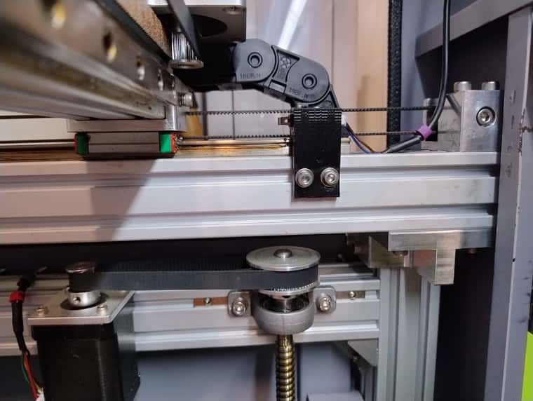
- If 4 independent motors solution is chosen, then drive mapping is needed. Please check the Duet instruction, and keep in mind that the printer is viewed from front. It works right as it is ment to work.
- The main board of the project is a 6XD, the second board being a CAN 3HC.
-
M208 X0:524 Y0:600 ; Xcarriage move, Ycarriage move M92 X80.00 Y160.00 Z2400.00 E932 ; set steps per mm M566 X900.00 Y900.00 Z60.00 E120.00 ; set maximum instantaneous speed changes (mm/min) M203 X6000.00 Y6000.00 Z180.00 E1200.00 ; set maximum speeds (mm/min) M201 X500.00 Y500.00 Z20.00 E250.00 ; set accelerations (mm/s^2) M906 X3000 Y3000 Z3000 E1500 I30 ; set motor currents (mA) and motor idle factor in per cent M84 S30 ; Set idle timeout ; Axis Limits M208 X0 Y0 Z0 S1 ; set axis minima M208 X525 Y601 Z800 S0 ; set axis maxima- The printer was a 2 extruder setup. However, as the heads were fixed, without some system to protect from part kicking, for wiping, etc, I decided to give up, and use one head.
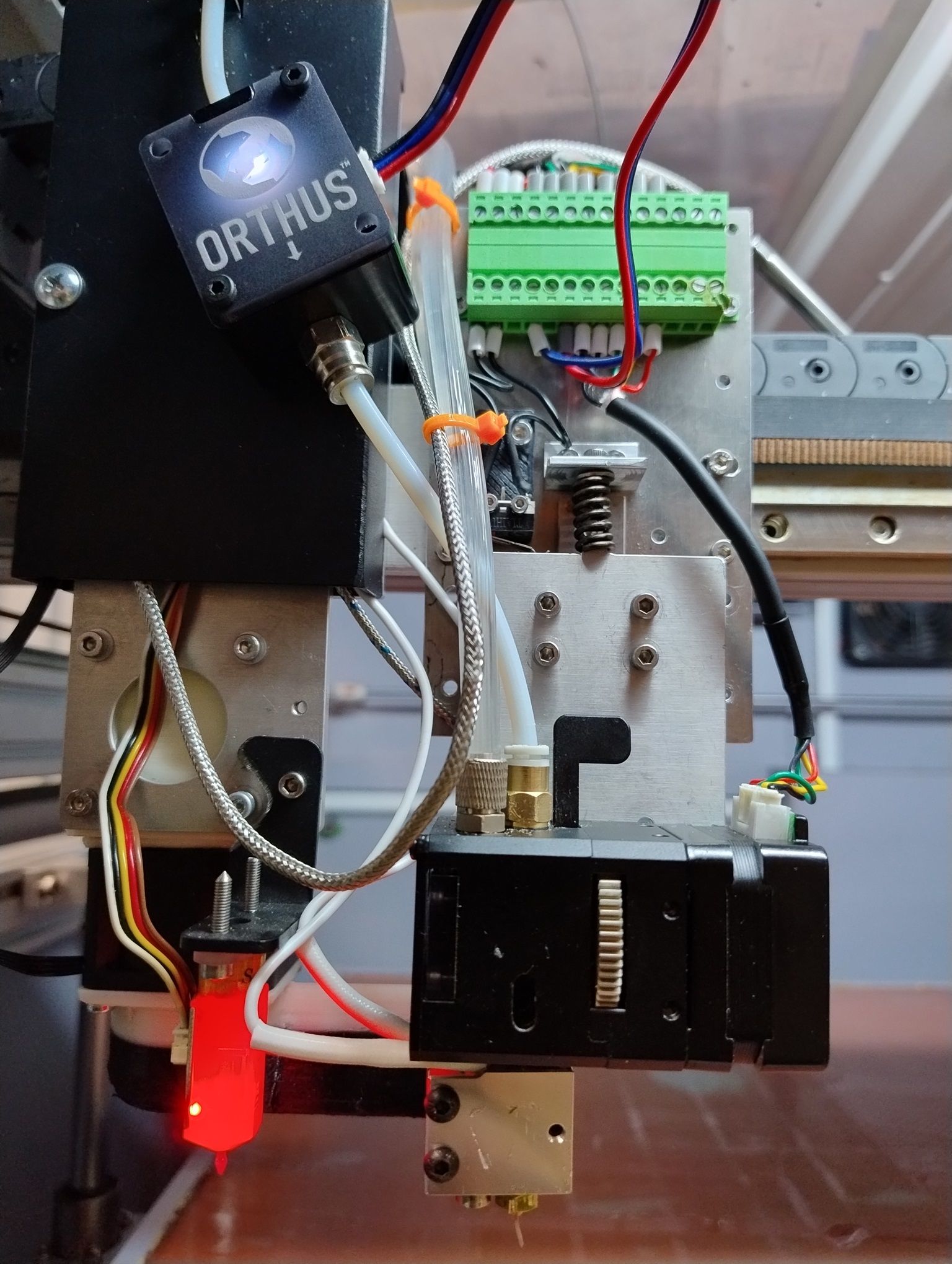
Because I was not in the mood for complex stuff, I used one support for 3d touch and cooling system, and the total area was somewhat reduced on X, that is why instead of 600mm I have available only 527 or so.
-
Steps per mm were calculated with Prusa calculator, as when used the configuration software I was in a complete darkness about all the stuff from there. Right now I cant tell how well the Configuration software does the same thing. Need some lecithin, maybe... Of course, for extruder one needs the specs from manufacturer. Mine being a BIQU H2O.
-
Regarding Hotend and extruder. For an enclosed printer, ESPECIALLY when needing to print PLA, PETG, ABS, one may need a water cooled one. It worth all the money.
BIQU H2O is an option, not necesarily the best. It works great, I got up to 40mm^3/s, with a Volcano on it (it comes with a smaller hotend, wich they say is capable of 45mm^3/s. Hmmm, well, maybe... The advantage of their hotend is that the heating element and sensor are horizontal.
The main ”flaw” is their throat, wich is 5.9mm diameter, not 6.9 like most of them. However, their bimetal throat comes with a flat face, wich makes an easy task for their 2x M3 grub screws to keep it in place. You may want to replace them with pointed ones, but it works as it is.
I did not find yet how the force exerted to filament cand be modified. If somebody knows, please enlighten me.
It is a powerful extruder, but small footprint. Because of this, one cant put the filament sensor directly on top, because of water cooling tubes. But is indeed lightweight. Original extruder had 1kg, and it went only up to 35mm^/s
- One interestring thing from DoWell, is the anticollision system, wich means that the extruder support is two part, one fixed on the X bearings, and one fixed on a dedicated vertical bearing, acting a microswitch.
It works, and it triggers... a trigger:
M950 J9 C"1.io3.in" ;define pin GPIO 9 1.io3.in M581 T4 P9 S0 R0 ; define trigger T5, pause on bed touch, acting on active /inactive edge pin GPIO 9, anytime- 3D Touch, works as intended, but the configuration was not clear to me from the Configuration software.
Of course, a clone is a clone, they are EXTREMELY buggy, I would recommend buy an original BL Touch, but I had many of these (half of them not working from factory).
; Z-Probe
M950 S0 C"io7.out"                                 ; create servo pin 0 for BLTouch
M558 P9 C"io7.in" H5 F120 T6000                    ; set Z probe type to bltouch and the dive height + speeds
G31 P500 X0 Y0 Z2.5                                ; set Z probe trigger value, offset and trigger height
No need to specify to check the pinout, and not assume any wire color, ehhh...? They have one GND pin more than needed, so adapt this as you see fit. I put them together in the connector (covered in this view, as I had only 4 wire cable already wired.
- Filament monitor.
This is a story. I hope that sometime in the future, Duet staff will dissasemble an Orthus, learn from it, keep what is best from DUET, and do a better sensor.
a. Duet PROs: metal wheels
b. Orthus PROs: all, EXCEPT wheels, as they are rubber. RUBBER! I would not have believed if I would not have some filament stuck there and need to check. So forget printing CF filament with Orthus.
; Filament sensors
;M591 P1 C"1.io0.in" S1 D0					  ; define simple microsw fil sensor at bd 1 inp 0, low is fil runout
;M591 D0 P3 C"1.io1.in" S1  ; filament monitor magnetic  duet
M591 D0 P7 C"1.io1.in" S1 R20:200 E10 L1.246 A0 ; filament magnetic monitor Orthus.
M591 it appears that it cant be used with more than one filament sensor per tool. Because of this, the other filament sensors need to be done by triggers. This is why the first M591 are commented.
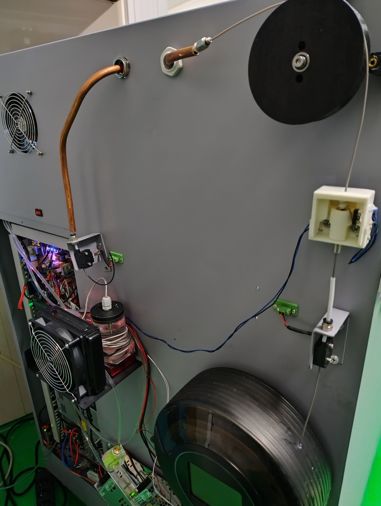
As you can see, I have another 3 filament sensors, two for filament over (wich does not works at once, so one needs to be disabled or filled with filament. It is a remnant from 2 head system, and I let it so.
The white one is a diameter sensor, wich is a simple throat acting a microswitch. It works as intended, but its place should have been on X gantry.
However, even if in theory one would need only the magnetic filament sensor, in practice, you may want to splice the filament outside the printer, so...The triggers for them are as follows:
M950 J6 C"1.io0.in"                     ;define pin GPIO 6 1.io0.in
M581 T2 P6 S0 R0		       ; define trigger T2, pause on filament left over, comutarea pe active /inactive edge pin GPIO 6, anytime
M950 J7 C"1.io3.in"                     ;define pin GPIO 7 1.io3.in
M581 T3 P7 S0 R0		       ; define trigger T3, pause on filament right over, comutarea pe active /inactive edge pin GPIO 7, anytime
M950 J8 C"1.io4.in"                     ;define pin GPIO 8 1.io4.in
M581 T4 P8 S0 R0		       ; define trigger T4, pause on filament decalibrated, comutarea pe active /inactive edge pin GPIO 8, anytime
And the files:
; trigger2.g
; called when filament is over - a print from SD card is paused

M118 P0 S"S-a terminat rola de filament, senzor stanga" L1
set global.decalibrache=0
M25 ;pause
; trigger3.g ; called when filament is over - a print from SD card is paused M118 P0 S"S-a terminat rola de filament, senzor dreapta" L1 set global.decalibrache=0 M25 ;pause; trigger4.g ; called when filament is too big diameter ; M118 P0 S"Filament decalibrat" L1 set global.decalibrache=1 M25As trigger 4 is a little special, because it means the filament is stuck, the head needs to stay on place, just rised from the part somewhat. That is why the variable is needed and defined in config.g (I could not have it defined iater, it did not worked, but I may have done something wrong).
; called when a print from SD card is paused
;
; generated by RepRapFirmware Configuration Tool v3.4.0 on Wed Dec 20 2023 17:08:52 GMT+0200 (Eastern European Standard Time)if global.decalibrache!=0 M98 P"pauza_pe_loc.g" else M98 P"pauza_acasa.g"So in pause.g we have a fork. I did it this way, with an external code, because at the moment, I was not aware that the indenting of code is very important with this interpreter, and it did not worked like in (the familiar) C. Eh, Phyton stuff...
Pause at filament decalibrated:
;pauza_pe_loc.g
;se lasa capul pe loc, putin ridicat, pentru a nu rupe filamentul
M83            ; relative extruder moves
G1 E-0.4 F1200  ; retract 0.4mm of filament
G91            ; relative positioning
G1 Z2 F360     ; lift Z by 2mm
;stay in place to not break the filament
;M568 P0 A1  ; set tool 0 heaters to their standby temperatures - this needs to be tested
set global.decalibrache=0
Pause at filament over (need to go home, if the filament is not spliced externally, wich is not yet the case for the moment)
;pauza_acasa.g ;go home for pause M83 ; relative extruder moves G1 E-0.4 F1200 ; retract 0.4mm of filament G91 ; relative positioning G1 Z2 F360 ; lift Z by 2mm G90 ; absolute positioning G1 X0 Y0 F3600 ; go to X=0 Y=0 - The printer was a 2 extruder setup. However, as the heads were fixed, without some system to protect from part kicking, for wiping, etc, I decided to give up, and use one head.
-
@soare0
Y motor. This is done quite ok, but changing the Y primary belt, may be a challenge, as there is much dissasembling to be done.
Belt tensioning is done from motor fixing screws, on the backplane, nothing special. For such a system, the bearing in center is a must.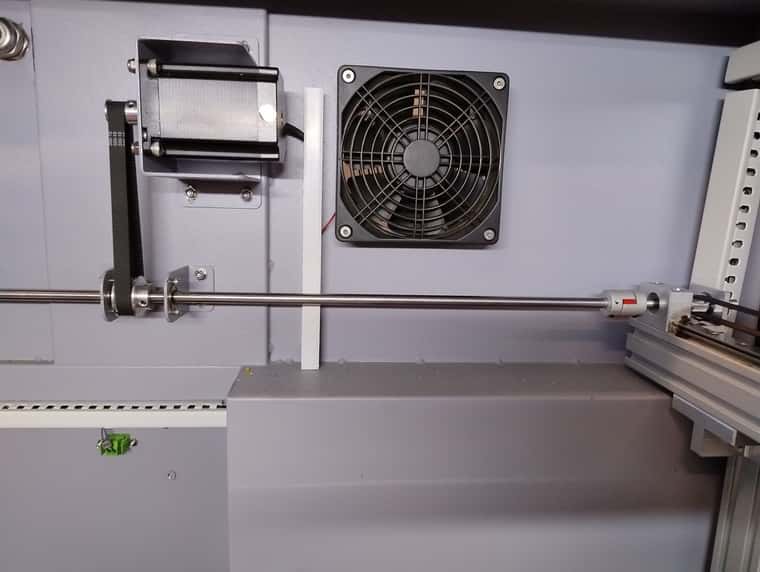
Volcano Hotend. This is still a good stuff, even if for really high flow, there may be other better solutions. However, its main disavantages, the heating element and sensor, are well... disavantages, at least for some.
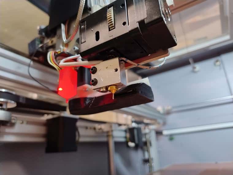
And, of course, most of you will do a better job with the cooling system. Still, the server fan, with PWM and tacho, is a nice thing, if one have the needed place to sacrifice. Probably a turbine would do an even better job, but this was the only PWM/tacho high flow 24V I could find that weekend.
-
@soare0
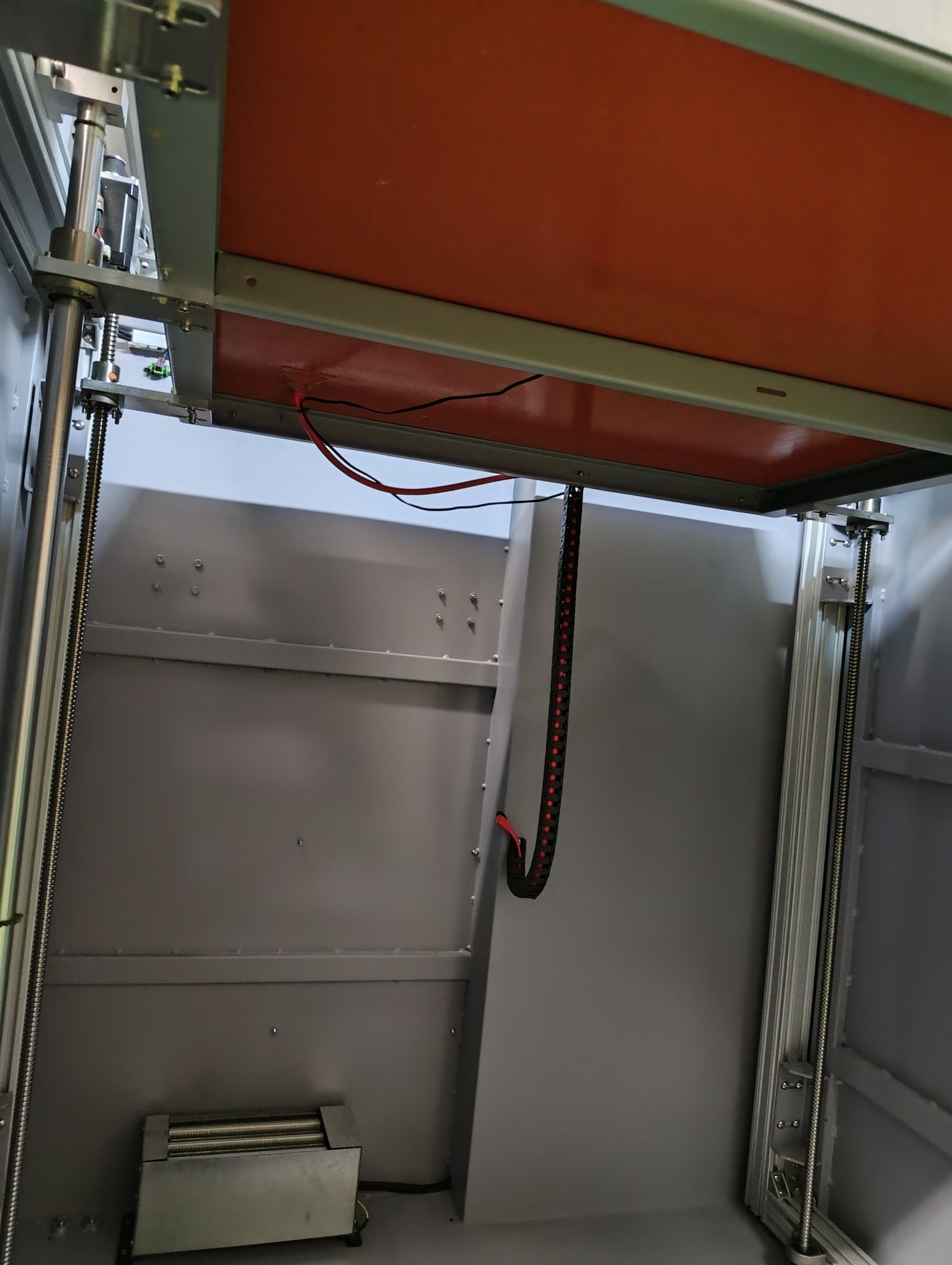
Under the ”belt” stuff.The PTC heather is a crap, No way to heat at 60C, but only with the bed at 100-120C, at the same time. Needs to be upgraded.
Regarding the heating pad, a custom one with a periferal zone and a central zone is a must for large beds. 10C gradient may have a huge impact. To be considered for the future, but indeed, I had problems with large parts, and high temperature bed. Up to 70C, it was okish. 90-130C, with 60C ambient, not so much.
If we are here, lets take a look at heaters:
; Heaters
M308 S0 P"temp0" Y"thermistor" T100000 B4138       ; configure sensor 0 as thermistor on pin temp0
M950 H0 C"out0" T0                                 ; create bed heater output on out0 and map it to sensor 0
M307 H0 B1 S1.00                                   ; enable bang-bang mode for the bed heater and set PWM limit
M140 H0                                            ; map heated bed to heater 0
M143 H0 S150                                       ; set temperature limit for heater 0 to 150C
M308 S1 P"1.spi.cs1" Y"thermocouple-max31856"      ; configure sensor 1 as thermocouple via CS pin 1.spi.cs0
M950 H1 C"1.out0" T1                               ; create nozzle heater output on 1.out0 and map it to sensor 1
M307 H1 B0 S1.00                                   ; disable bang-bang mode for heater  and set PWM limit
M143 H1 S400                                       ; set temperature limit for heater 1 to 400C
M308 S2 P"temp1" Y"pt1000"                         ; configure sensor 2 as pt1000 via temp1
M950 H2 C"out8" T2                                 ; create main chamber heater output on out8 and map it to sensor 2
M307 H2 B1 S1.00                                   ; enable bang-bang mode for heater  and set PWM limit
M141 P0 H2                                         ; map chamber0 to heater 2
M143 H2 S80                                        ; set temperature limit for heater 2 to 80C

M308 S3 P"1.temp2" Y"pt1000"  A"Water_E0"            ; configure sensor 3 as pt1000 via 1.temp2

M308 S4 P"1.temp1" Y"thermistor"  A"Fil_CH"         ; configure sensor 4 as thermistor via 1.temp1
M950 H4 C"1.out1" T4                               	; create  filament heater output on 1.out7 and map it to sensor 4
M307 H4 B1 S1.00                                  	; enable bang-bang mode for heater  and set PWM limit
M141 P1 H4                                          ; map chamber1 to heater 4
M143 H4 S100                                        ; set temperature limit for heater 1 to 100C
The only thing somewhat special is the dual chamber heating, wich did not worked well in 3.4.6, but in 3.5 rc2, does.
Oh, and pair the heater and sensor on the same board, whatever it would be. I had problems with that, apparently, and if I remember right, this is told somewhere.
Chamber 0 is main chamber, Chamber 1 is filament heater, wich is a modified commercial one (just used the PTC heater from it). It is mounted on the backplane. I used it because it was on the shelf, it has rollers, and it works at 24V.
Sensor 3 is just for fun, as I wanted to have the cooling water temperature displayed on DWCAs it was difficult to tune some heaters, I simply got out the fault stuff from them. The printer cant get on (serious) fire but maybe with some propane torch, so:
;heaters fault detection
M570 H2 P9999 T60
M570 H1 P9999 T90
M570 H0 P9999 T150
M570 H4 P9999 T100
Now, this is unprofessional, but I got the printer to work. For now.
Fans:
; Fans
M950 F0 C"!1.out3+out3.tach" Q500                 ; create fan 0 on pin 1.out3 and set its frequency. Part cooling fan
M106 P0 S1 C"Aer_E0" H-1                            ; set fan 0 value. Thermostatic control is turned off
M950 F1 C"1.out6" Q500                              ; create fan 1 on out6 and set its frequency
M106 P1 S1  H1 T45                                  ; set fan 1 value. Thermostatic control senzor 1 is turned on. Water pump motor
M950 F2 C"out7" Q500                                ; create fan 2 on out7 and set its frequency
M106 P2 S1 C"Camera" H2 T65                         ; set fan 2 value. Thermostatic control senzor 2 is turned on. Main chamber cooling fan
F0 and F1 are in the order recommended by RRF, F0 for part cooling, and F1 for extruder cooling.
In this setup, F1 is a water pump, also from BTT. It works nice, just I needed another PSU, 12V, and a little trick to connect at the 6XD. Better to use some 24V/12V step down, but for some reason I did it this way.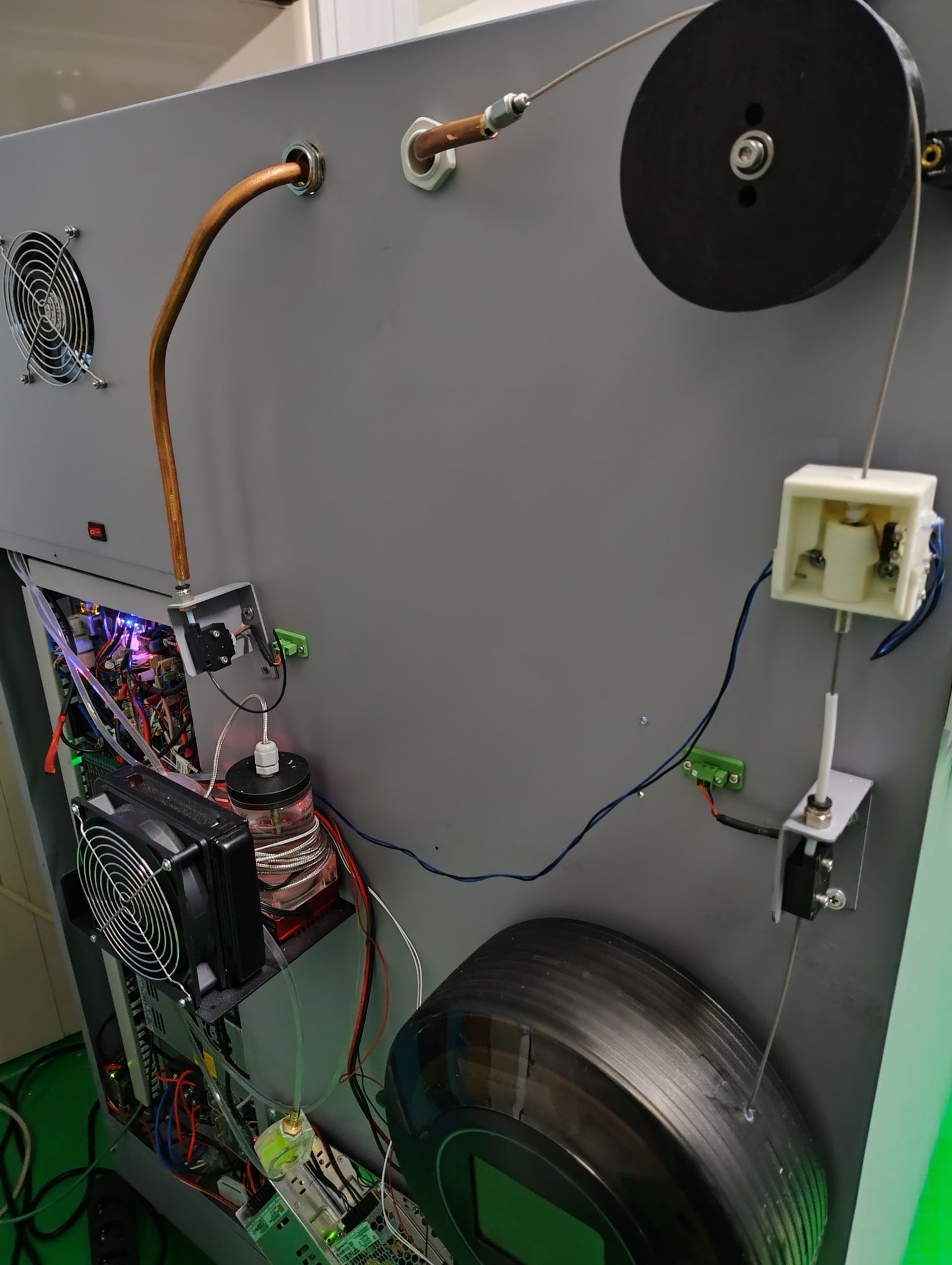
The flow turbine is a good addition, but take care to use it so the water will flow from bottom through it.
The spiral on the water reservoir, is just me not in the mood to shorten the sensor wire.
Of course, having electronics in the path of some water drops, is never a good ideea. Some separation will be added soon between the pump and the 2 PSUs below, one of them being the 5V for RPI5 (not used yet). This was a pain to connect to RPI, because of the lack of good USB C cables.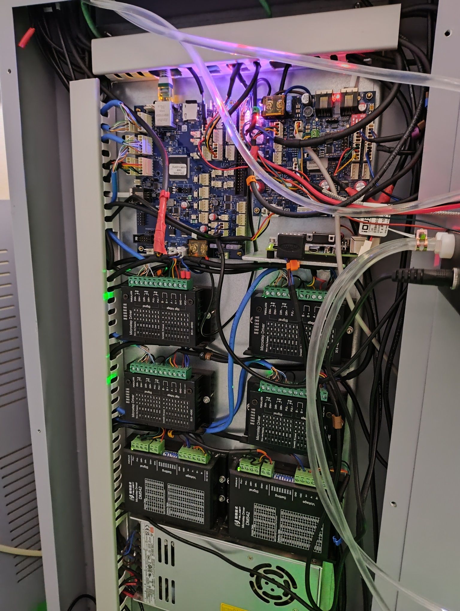
Electronics is nothing special. DoWell guys used common stuff, but unlike the bearings, at least the PSU and stepper drivers are ok, and were set for the original motors. For this, I thank them...
They also head some circuitry for power loss, and startup, wich were thrown at the bin. However, they could have been used, but I am an easy bin thrower.
The only thing wich gave me a little headache, was that they used two type of stepper drivers, wired differently, one with common GND, and one with common VDD, and I needed to adapt the wiring to 6XD, so needed a little rewiring. As this will depend on your driver type, just follow their datasheet, and keep in mind that on 6XD the outputs are OPEN DRAIN (lecithin needed, again).
NOTE: If you are working with multiple PSUs, take care to have a common ground wire between all of them.
I am specifying this because until these days I thought it is common knowledge/sense. Of course, this may or may not apply to the situation where some optical insulation is needed, for CMMR reasons, noisy circuits and such.
Of course, one may take into account how the power is drained from them, as the common ground is usual needed for potential reference. The heathers, etc, need to be wired accordingly, separating, as much as possible the curent flows.
This note is intended for those without a somewhat deeper insight in electrical engineering, albeit it is nothing really ”deep” in this. Only you will deeply fry something or many things if you will not wire multiple boards/heathers/PSUs right. -
@soare0 Finally, many thanks to Duet support. Honestly, I wanted to pay some support guys, as gcode scared me at first, and was mentally prepared to pay ... a good amount for this (more than I paid for DUET electronics). However, as I could not find any real paid support (albeit promised from one reseller), the forum (on the condition of reading the documentation, and some/many lost nights), was helpful enough.
However, I could not recommend this for anybody. I saw some failures here, for some who stretched too much with big projects, hoping to spare some money. But if learning is the goal, or needed skills are already there, this is a good place.
I heard here and there that DUET is too expensive.
It is not. Because of the best UNPAID support.