Wiring a Duet 3 Scanning Z-Probe v1.0 to a Toolboard v1.3
-
@droftarts the black and white wires are coming from the TDB and going to the 1LC. As well as the white and green are coming from the same TDB and going to the SZP. Are we saying the same thing? Are you saying that I should daisy chain the CAN from the 1LC to the SZP and not from the TDB?
-
@WOPR73 no, I’m saying it goes from the TDB to the 1LC (black and white wires), then to the SZP (wires I drew), then back to the TDB (yellow and green wires). No termination on the 1LC or SZP, termination on the TDB.
Ian
Bed-slinger - Mini5+ WiFi/1LC | RRP Fisher v1 - D2 WiFi | Polargraph - D2 WiFi | TronXY X5S - 6HC/Roto | CNC router - 6HC | Tractus3D T1250 - D2 Eth
-
@WOPR73 on the TDB, think of the black and white wires being ‘out’, and the green and yellow being ‘in’. It needs to be a loop from ‘out’ to ‘in’. There aren’t two ‘outs’ on one header.
Ian
Bed-slinger - Mini5+ WiFi/1LC | RRP Fisher v1 - D2 WiFi | Polargraph - D2 WiFi | TronXY X5S - 6HC/Roto | CNC router - 6HC | Tractus3D T1250 - D2 Eth
-
@droftarts I got it! It the cable I modified was just plugged into the TDB and 1LC in reverse. SWEET!!! B0, B120 and B121 talking!
5/2/2024, 7:59:07 PM M122 B120
Diagnostics for board 120:
Duet SZP firmware version 3.5.0-rc.1+ (2023-11-20 12:50:20)
Bootloader ID: SAMC21 bootloader version 2.10 (2023-11-16)
All averaging filters OK
Never used RAM 14484, free system stack 136 words
Tasks: HEAT(2,nWait,0.1%,131) CanAsync(5,nWait,0.0%,55) CanRecv(3,nWait,0.0%,79) CanClock(5,nWait,0.0%,67) ACCEL(3,nWait,0.0%,53) MAIN(1,running,99.7%,434) IDLE(0,ready,0.0%,27) AIN(2,nWait,0.2%,92), total 100.0%
Last reset 00:00:44 ago, cause: power up
Last software reset data not available
Peak sync jitter 6/10, peak Rx sync delay 198, resyncs 0/0, no timer interrupt scheduled
VIN voltage: min 4.9, current 4.9, max 5.0
MCU temperature: min 27.1C, current 27.2C, max 27.3C
Last sensors broadcast 0x00000000 found 0 248 ticks ago, 0 ordering errs, loop time 0
CAN messages queued 195, send timeouts 0, received 564, lost 0, errs 1, boc 0, free buffers 18, min 18, error reg 20000
Accelerometer: LIS2DW, status: 00
Inductive sensor: raw value 36434439, frequency 3.39MHz, current setting 13, ok
I2C bus errors 139, naks 3, contentions 0, other errors 05/2/2024, 7:59:05 PM M122 B121
Diagnostics for board 121:
Duet TOOL1LC rev 1.1 or later firmware version 3.5.1 (2024-04-19 14:42:41)
Bootloader ID: SAMC21 bootloader version 2.4 (2021-12-10)
All averaging filters OK
Never used RAM 4152, free system stack 132 words
Tasks: Move(3,nWait 7,0.0%,129) HEAT(2,nWait 6,0.2%,129) CanAsync(5,nWait 4,0.0%,55) CanRecv(3,nWait 1,0.0%,71) CanClock(5,nWait 1,0.0%,61) ACCEL(3,nWait 6,0.0%,53) TMC(2,nWait 6,3.4%,53) MAIN(1,running,91.8%,315) IDLE(0,ready,0.0%,27) AIN(2,delaying,4.6%,114), total 100.0%
Owned mutexes:
Last reset 00:00:42 ago, cause: power up
Last software reset data not available
Driver 0: pos 0, 80.0 steps/mm, standstill, SG min 0, read errors 0, write errors 0, ifcnt 9, reads 21055, writes 9, timeouts 0, DMA errors 0, CC errors 0, steps req 0 done 0
Moves scheduled 0, completed 0, in progress 0, hiccups 0, segs 0, step errors 0, maxLate 0 maxPrep 0, maxOverdue 0, maxInc 0, mcErrs 0, gcmErrs 0, ebfmin 0.00 max 0.00
Peak sync jitter 5/9, peak Rx sync delay 205, resyncs 0/0, no timer interrupt scheduled
VIN voltage: min 24.7, current 24.7, max 24.7
MCU temperature: min 32.2C, current 35.0C, max 35.1C
Last sensors broadcast 0x00000002 found 1 146 ticks ago, 0 ordering errs, loop time 0
CAN messages queued 829, send timeouts 0, received 381, lost 0, errs 1, boc 0, free buffers 18, min 18, error reg 20000
dup 0, oos 0/0/0/0, bm 0, wbm 0, rxMotionDelay 0
Accelerometer: LIS3DH, status: 00
I2C bus errors 0, naks 3, contentions 0, other errors 05/2/2024, 7:59:03 PM M122 B0
=== Diagnostics ===
RepRapFirmware for Duet 3 MB6HC version 3.5.1 (2024-04-19 14:30:55) running on Duet 3 MB6HC v1.01 (standalone mode)
Board ID: 08DJM-956L2-G43S8-6J1D6-3SJ6K-KA06G
Used output buffers: 1 of 40 (26 max)
Error in macro line 60 while starting up: invalid Z probe index
=== RTOS ===
Static ram: 155208
Dynamic ram: 120424 of which 100 recycled
Never used RAM 67404, free system stack 204 words
Tasks: NETWORK(1,ready,35.7%,140) ETHERNET(5,nWait 7,0.1%,317) HEAT(3,nWait 6,0.0%,329) Move(4,nWait 6,0.0%,336) CanReceiv(6,nWait 1,0.0%,795) CanSender(5,nWait 7,0.0%,334) CanClock(7,delaying,0.0%,348) TMC(4,nWait 6,9.2%,56) MAIN(1,running,52.3%,105) IDLE(0,ready,2.6%,30), total 100.0%
Owned mutexes: HTTP(MAIN)
=== Platform ===
Last reset 00:00:39 ago, cause: power up
Last software reset at 2024-05-02 19:18, reason: User, Gcodes spinning, available RAM 70272, slot 1
Software reset code 0x0003 HFSR 0x00000000 CFSR 0x00000000 ICSR 0x00400000 BFAR 0x00000000 SP 0x00000000 Task MAIN Freestk 0 n/a
Error status: 0x00
Aux0 errors 0,0,0
MCU temperature: min 20.5, current 29.2, max 29.2
Supply voltage: min 24.1, current 24.1, max 24.2, under voltage events: 0, over voltage events: 0, power good: yes
12V rail voltage: min 12.1, current 12.2, max 12.3, under voltage events: 0
Heap OK, handles allocated/used 99/2, heap memory allocated/used/recyclable 2048/32/0, gc cycles 0
Events: 0 queued, 0 completed
Driver 0: standstill, SG min n/a, mspos 8, reads 21473, writes 16 timeouts 0
Driver 1: standstill, SG min n/a, mspos 8, reads 21473, writes 16 timeouts 0
Driver 2: standstill, SG min n/a, mspos 8, reads 21473, writes 16 timeouts 0
Driver 3: standstill, SG min n/a, mspos 8, reads 21473, writes 16 timeouts 0
Driver 4: standstill, SG min n/a, mspos 8, reads 21478, writes 11 timeouts 0
Driver 5: standstill, SG min n/a, mspos 8, reads 21479, writes 11 timeouts 0
Date/time: 2024-05-02 19:59:02
Slowest loop: 3.32ms; fastest: 0.07ms
=== Storage ===
Free file entries: 20
SD card 0 detected, interface speed: 25.0MBytes/sec
SD card longest read time 2.2ms, write time 0.0ms, max retries 0
=== Move ===
DMs created 125, segments created 0, maxWait 0ms, bed compensation in use: none, height map offset 0.000, max steps late 0, min interval 0, bad calcs 0, ebfmin 0.00, ebfmax 0.00
no step interrupt scheduled
Moves shaped first try 0, on retry 0, too short 0, wrong shape 0, maybepossible 0
=== DDARing 0 ===
Scheduled moves 0, completed 0, hiccups 0, stepErrors 0, LaErrors 0, Underruns [0, 0, 0], CDDA state -1
=== DDARing 1 ===
Scheduled moves 0, completed 0, hiccups 0, stepErrors 0, LaErrors 0, Underruns [0, 0, 0], CDDA state -1
=== Heat ===
Bed heaters 0 -1 -1 -1 -1 -1 -1 -1 -1 -1 -1 -1, chamber heaters -1 -1 -1 -1, ordering errs 0
=== GCodes ===
Movement locks held by null, null
HTTP is ready with "M122 B0" in state(s) 0
Telnet is idle in state(s) 0
File is idle in state(s) 0
USB is idle in state(s) 0
Aux is idle in state(s) 0
Trigger is idle in state(s) 0
Queue is idle in state(s) 0
LCD is idle in state(s) 0
SBC is idle in state(s) 0
Daemon is idle in state(s) 0
Aux2 is idle in state(s) 0
Autopause is idle in state(s) 0
File2 is idle in state(s) 0
Queue2 is idle in state(s) 0
Q0 segments left 0, axes/extruders owned 0x0000000
Code queue 0 is empty
Q1 segments left 0, axes/extruders owned 0x0000000
Code queue 1 is empty
=== CAN ===
Messages queued 355, received 923, lost 0, errs 1, boc 0
Longest wait 2ms for reply type 6053, peak Tx sync delay 68, free buffers 50 (min 49), ts 199/198/0
Tx timeouts 0,0,0,0,0,0
=== Network ===
Slowest loop: 5.33ms; fastest: 0.03ms
Responder states: MQTT(0) HTTP(0) HTTP(0) HTTP(0) HTTP(0) HTTP(0) HTTP(0) FTP(0) Telnet(0) Telnet(0)
HTTP sessions: 1 of 8
= Ethernet =
Interface state: active
Error counts: 0 0 0 1 0 0
Socket states: 5 2 2 2 2 0 0 0
=== Multicast handler ===
Responder is inactive, messages received 0, responses 0 -
@droftarts It seems to be working! Thank you soooo much! Everyone is blinking in uncini.
-
-
Thank you once again. Great help! Thanks!


-
@WOPR73 that’s not quite how I told you to wire it, but it works because, I assume, you have termination on the SZP?
The problem you will have in the future that the CAN bus continues no further than the SZP, so you can’t connect anything else to the TDB. The TDB isn’t like an Ethernet hub. It’s not a star topology network. See the wiring diagram for the TDB here: https://github.com/Duet3D/Duet3-Tool-Distribution-Board/blob/master/Tool Distribution v0.5/Duet3_Tool_Breakout_Schematic_v0.5.pdf
It loops on CAN connection to the next. At the moment, you have no return from the SZP. If you wire from SZP back to the TDB, you’ll need to remove termination on the SZP and terminate on the TDB.I think it may also be possible to wire it as a stub, but we recommend that stubs are under 1m long, and usually only have one toolboard on each stub, whereas you have two. For this, put the bypass jumpers back on, remove the termination on the SZP, and terminate on the TDB.
If that’s too confusing, let me know and I’ll draw a diagram.
Ian
Bed-slinger - Mini5+ WiFi/1LC | RRP Fisher v1 - D2 WiFi | Polargraph - D2 WiFi | TronXY X5S - 6HC/Roto | CNC router - 6HC | Tractus3D T1250 - D2 Eth
-
@droftarts Yeah, I was wondering about that. I think I have more of an understanding of how CAN works with the TDB and other CAN devices plus what the repercussions to soldering that 120 resistor bridge would be. As for now I just need to get this up and running with all the Duet 3 hardware configured. Just finding the correct commands for each piece of hardware is a little overwhelming. I the best that I have found for commands in the Reference/Gcodes. It's not how I though Gcode commands would work. But, this is some default code put in via RRF.
Example:; Probes
M558 K0 P11 C"120.i2c.ldc1612" H5 F120 T6000 ; configure scanning probe via slot #0
G31 P500 X0 Y0 Z0.7 ; set Z probe trigger value, offset and trigger heightNow I need to go through and look up and configure each device and its specific parameters... and verify with the manufactures data sheets. I guess step at a time.

Thanks again!
-
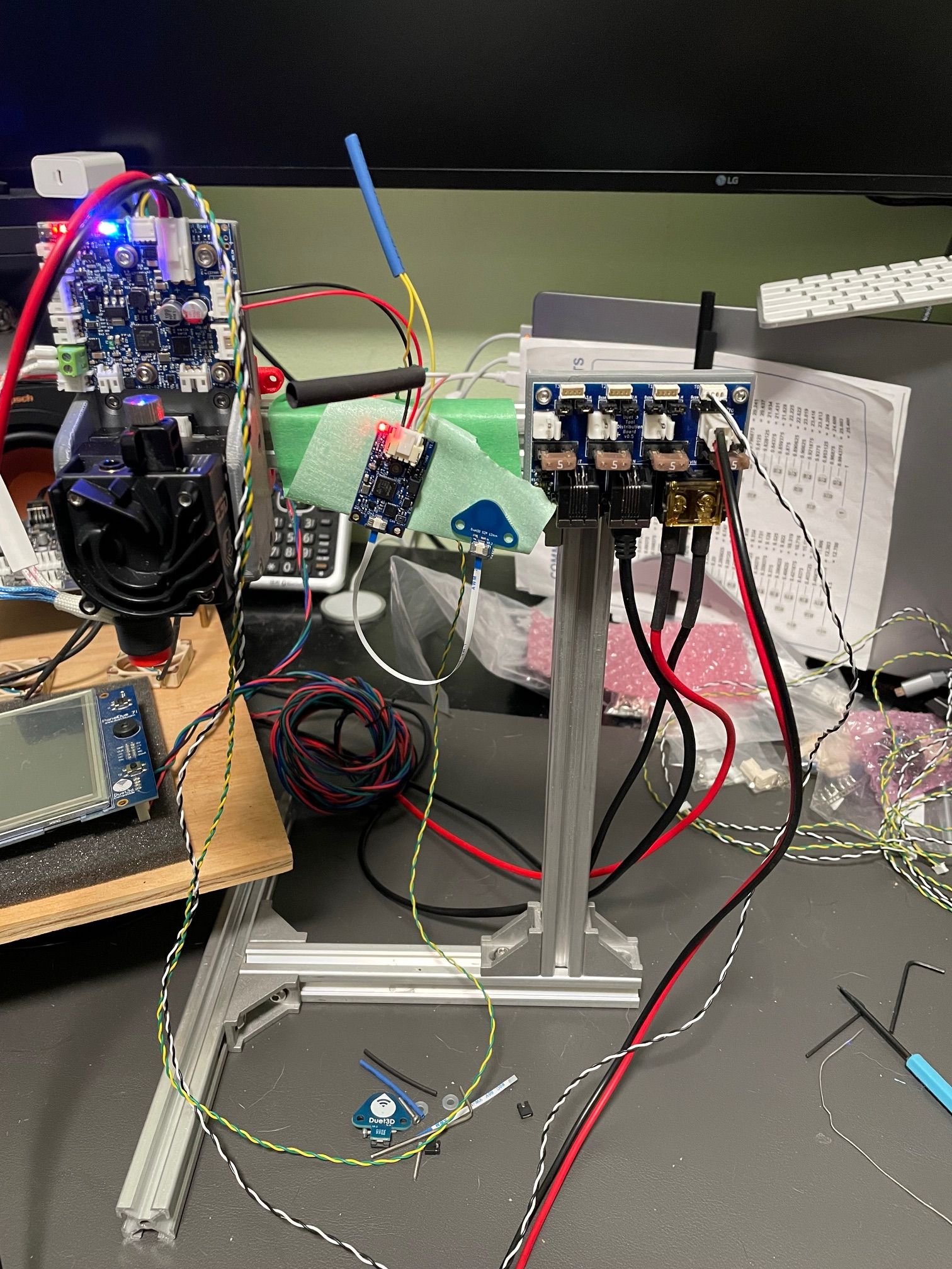
@droftarts I have more time to work on this again. So, I am going from the TDB (Black and White) to the 1LC, then from 1LC (yellow and green) going to the SZP. I do have the termination joined on the SZP. Is that not what you were trying to tell me?
-
@dc42 I was wondering if you could check out the last photo diagram I posted to make sure that I have configured the 1LC and SZP correctly. I am having a hard time finding complete detailed information on many of the Duet product lines. Even the hardware boxes didnt provide information. examples:
Both Images take you to this page.

I really would like to find a complete configuration for Duet3 hardware like what I have bought. I am not sure why there is not, but I do not find anything anywhere on the net.
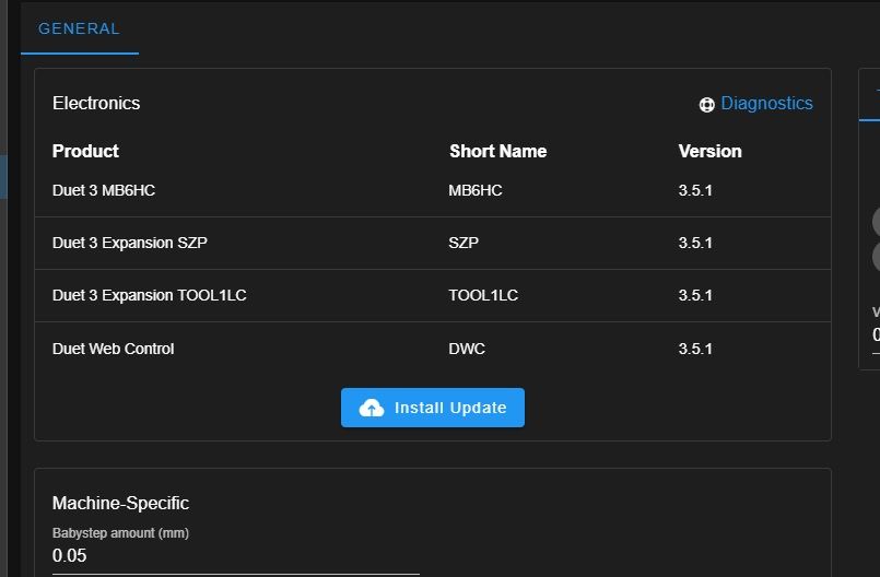
Duet 3 6HC v1.01
Duet 3 Tool Distribution Board v.05
Duet 3 Toolboard 1LC v1.3
Duet 3 Scanning Z-Probe v1.0
Duet PanelDue 7i
Duet Filament Monitor
with a
SBC: Raspberry Pi 4After reading the main Duet 3 Mainboard 6HC hardware overview... then what? It seems that there is a few steps missing from how to connect other Duet hardware together and configure the software end. I found myself bouncing back and forth on Github to just install the 3.5.1 files... due to the incompatibly of the 3.5.0 files that the RRF config tool gives you in the config.zip. DWC will complain of incompatibly mixing 3.5.0 and 3.5.1 files. So, now I can only copy and past bits and pieces of the config that I've built out to match the hardware I have so that there will be less guess work that I have to do to find the needed parameters. I find myself in a guessing game of commands to use for each hardware and what each connection can be used for.
So, I am asking... is there something I am missing. Some start page that is more complete for each of these products. I have been to FB forums and well... "...read the fucking documents..." seems to be a remark that a few leave... and a couple will tell you to go to the Forums and ask. I have no problem doing the leg work, but this seems incomplete on data and how things mesh together. There is more information on how to configure other manufactures hardware than Duets own.
Any help provided I would be greatly appreciated.
-
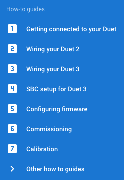
@WOPR73 on the wiki page, on the main menu in blue on the left hand side, have you seen the “How to guides"? These should guide you through connecting most peripherals to the mainboard. Connecting to toolboards is largely the same. It also guides you through configuration, commissioning and tuning.
The nature of the Duet ecosystem creates many unique and varied implementations. It’s impossible to document every single permutation. There is a huge amount of documentation for connecting and configuring devices, I think you haven’t explored the wiki pages. See https://docs.duet3d.com/en/User_manual/Connecting_hardware
Links for all the Duet boards hardware pages are here: https://docs.duet3d.com/en/Duet3D_hardware/Duet_3_family
Those pages have details on connecting and configuration that is specific to each board, while more general connections are linked to other pages, to avoid too much duplication of text. It would be nice to be able to have all information for your setup on one page, but it would be a very long page! The configtool also has links to specific wiki page for each section.Thanks, I’ll check what firmware files the config tool provides. -> Yes, the firmware version bundled appears to be 3.5.0-rc.3, not 3.5.1. This should be rectified today. -> Fixed now. You may need to clear your browsers 'Cached Web Content' and redownload the config.zip file to get the updated version.
The configuration files it generates work with all versions of 3.5 (beta, release candidate and release), and will mostly work with older versions back to RRF 3.0, though there have been changes over time. There's also the 'legacy' version for older versions.
While you absolutely should use the same version of RRF on mainboard and toolboards, and we recommend using the same version of DWC and RRF, there's a bit more leeway with the version of DWC. The incompatibility notice is more to remind you to update it.
Are you actually running in SBC mode, with the Raspberry Pi? You should follow the instructions here: https://docs.duet3d.com/User_manual/Machine_configuration/SBC_setup
Updating: https://docs.duet3d.com/User_manual/Machine_configuration/SBC_setup#update-firmwareIf running in standalone mode, updating firmware and DWC is covered here: https://docs.duet3d.com/User_manual/RepRapFirmware/Updating_firmware#usual-procedure
Thanks, I’ll check why the QR code isn’t working; probably just the link is incorrect. -> fixed now.
Ian
-
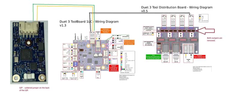
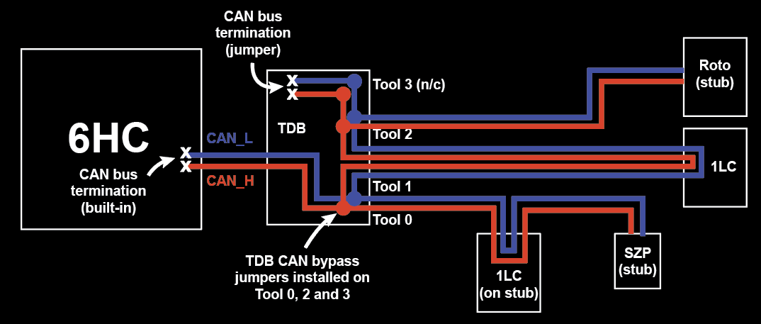
@WOPR73 Regarding your wiring, it is fine... for now. It's set up like this:
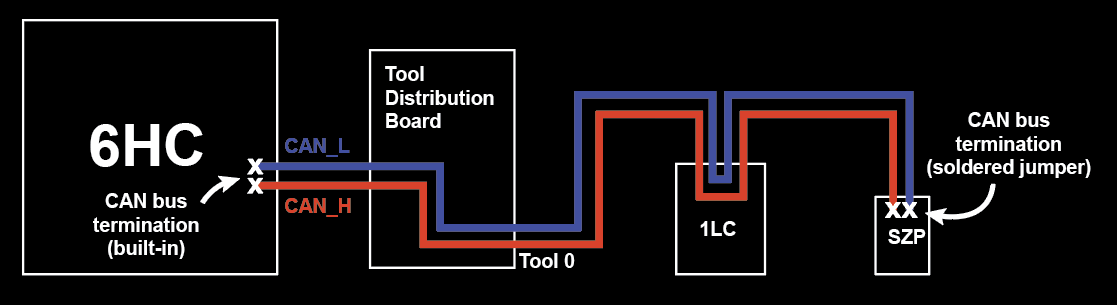
(Note: diagram for illustrative purposes only to show how CAN bus connects, pinout on boards may not be correct)As you can see, the Tool Distribution Board isn't doing much. It will work, but as I said before here https://forum.duet3d.com/post/338611, you won't be able to add any more toolboards connected to the Tool Distribution Board, as currently the CAN bus ends at the Scanning Z Probe. To enable the other Tool # outputs on the TDB, you need to:
- Desolder the termination jumper on the back of the SZP
- Refit the two jumpers below the 'Tool 0' connection on the TDB (which allows the bus to carry on to 'Tool 1' connection)
- Ensure the CAN termination jumper is fitted on the TDB
With the above, the 1LC and SZP connected to 'Tool 0' on the TDB are wired as a 'stub' off the main CAN bus. This means the maximum length of the whole 'stub' (from TDB to 1LC to SZP) needs to be 1m maximum. It's okay to have the 1LC and SZP on the same stub. To maximise the length between the 1LC and the TDB, keep the wires between 1LC and SZP as short as possible. You could end up with something like this:
When you add further tools, you can either wire them as 1m-long 'stubs' like Tool 0 (eg the Roto toolboard on Tool 2), or run the CAN bus to the toolboard and back, like the standard 1LC wiring (eg the 1LC on Tool 1), which can then be a much longer length. Note that the combined total of all stubs should be less that 5m.
Ian
Bed-slinger - Mini5+ WiFi/1LC | RRP Fisher v1 - D2 WiFi | Polargraph - D2 WiFi | TronXY X5S - 6HC/Roto | CNC router - 6HC | Tractus3D T1250 - D2 Eth
-
@droftarts Thank you for the information. And yes, I have seen all the information above. Most I have not tried, but have read them. I wanted to get the boards correct setup and talking so that do not run into more issue like this down the line. I am new to hardware config and did have the the 6HC wired long ago for motors, hotend, fans and inductive probe. But, once adding CAN things became a bit unclear how to connect things. The above diagrams are nice, but, unclear. Which pinout are you connecting too? I am going from tool 0 on the TDB using CAN 3)CAN1_L and CAN 4) CAN1_H, connecting to CAN-FD 1,2,3,4 ? and going from 1LC to the SZP 1,2,3,4? from where to where on the SZP CAN 1,2,3,4? Is this all using one set TDB CAN wire or two? Am I having to rewire one of the connections? If so, which and how. example?
6HC
1)nc
2)CAN0_H
3)CAN1_H
4)CAN1__L
5)CAN0_L
6)ncTDB
Tool0
1)CAN_L_0-1
2)CAN_H-0-1
3)CAN1_L
4)CAN1_H1LC
CAN-FD
1)CAN_L
2)CAN_H
3)CAN_L
4)CAN_HSZP
Ground
+5v
C_L
C_HI know that all of this seems very rudimentary for you as if everyone should understand. But, it is not straight forward. I am not trying to be difficult I just want to understand how things should be connected without magic blue smoke. For example.
https://docs.duet3d.com/User_manual/Connecting_hardware/Z_probe_connecting
The example given for the BL touch, should be about the SZP and not the touch. That would be much more helpful AND promote Duet products as an all in one solution. Instead I know more about the BL touch then the SZP. Making better sub categories with short and concise "how to" for Duet 3 6HC and SZP. then another for Duet 3 6HC +1LC + SZP. Then another for Duet 3 6HC + TDB + 1LC+ SZP. Then do the same for the other Duet mainboards. It would cut down on questions in the forums and the very toxic people. K.I.S.S is the goal... then people would be drawn to Duet and not BTT and others. Less chance for blue smoke and better chance of positive paying customers. The very few video out on the Duet and more on CNC then printers... and to be honest they are not that helpful in most cases. So, I just want to stay again... I am not trying to be rude or difficult. But, we go from the duet 3 family intro... to deep in the weeds for so many things that are not Duet. configure a secondary z-probe, but we have not even started on setting up our first.
Maybe another way to look at things...
If I want to confiugure 6HC, what commands are needed to be entered into the config.g for it to work as a printer.what commands for the: LC1
what commands for the : SZP
what commands for the : MFMI like the RRF tool. is gets you started. But, then what. how do you know where to go from there? How do I know what commands are needed if any at all? So, should everything work after the RRF? Do you see where the next steps are not so easy to figure out?
well, either way. I have just DE soldered the jumper, refit the two jumpers back on CAN 0 and the TDB jumper is still connected. I am using SBC now. I did in the start. But, removed it all and started troubleshooting. then I added SBC back into the mix once things were talking. I'll go back and reread everything you posted and see if I can figure out the wiring above.
Thank you for your help.