Duet 2 Frequency Step Signal Output Problem
-
I apologize for not using standard/correct industry terminology.
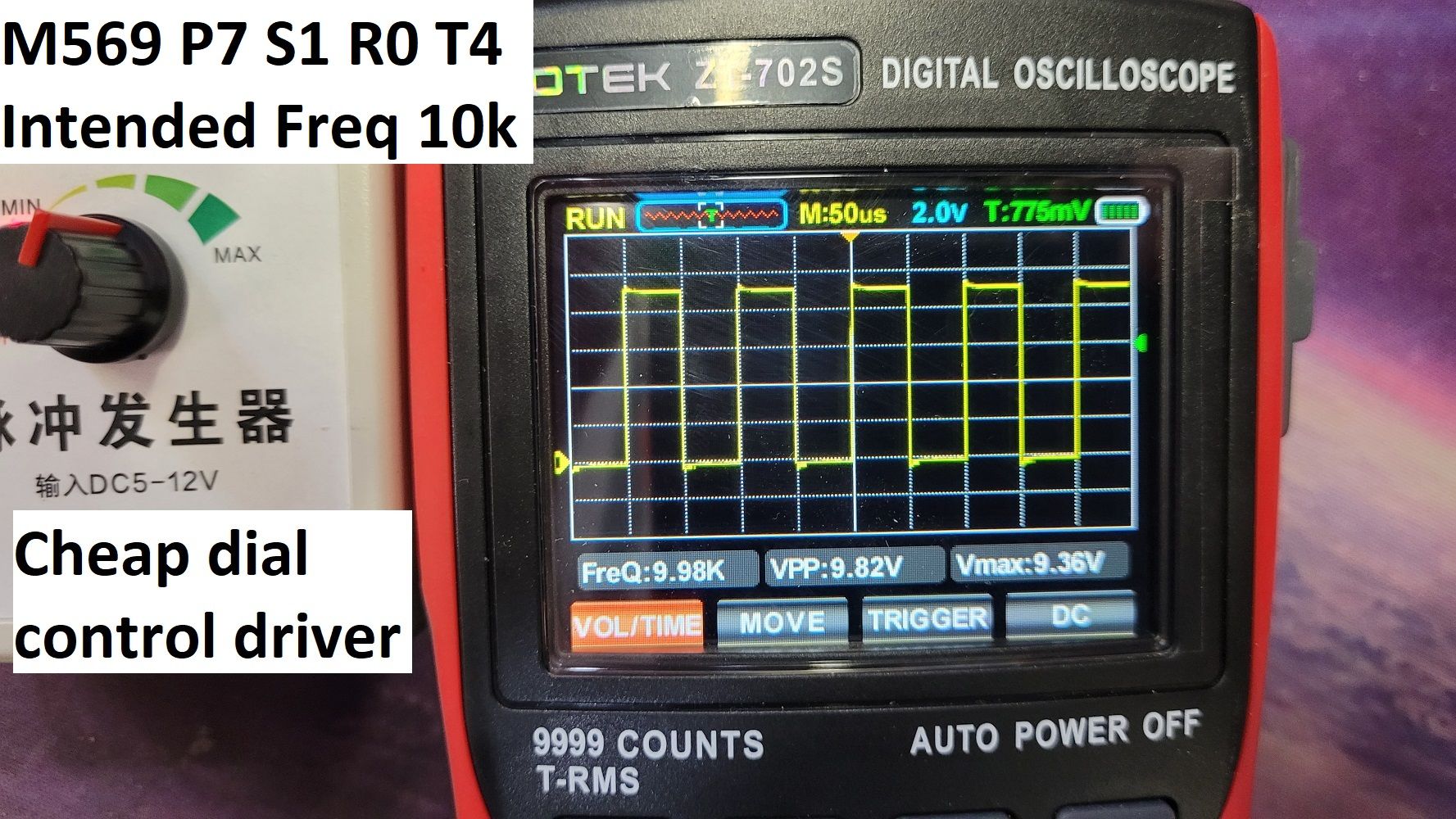
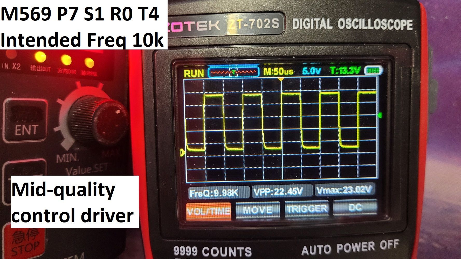
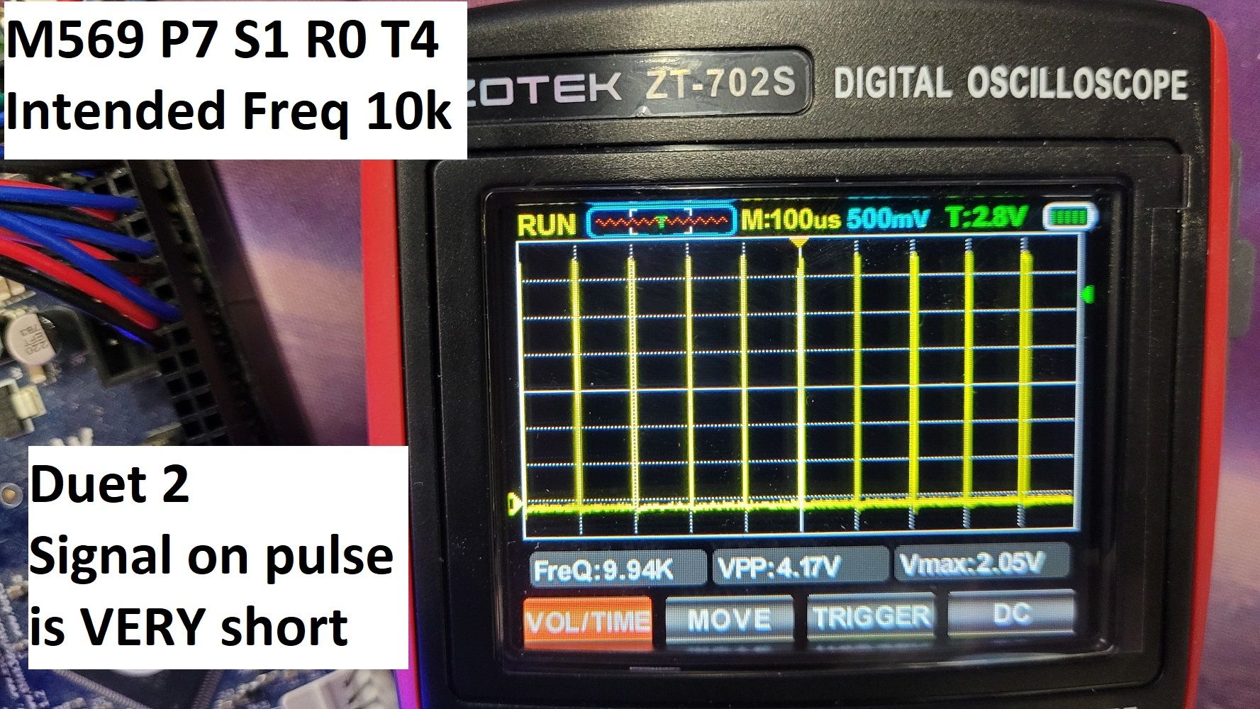
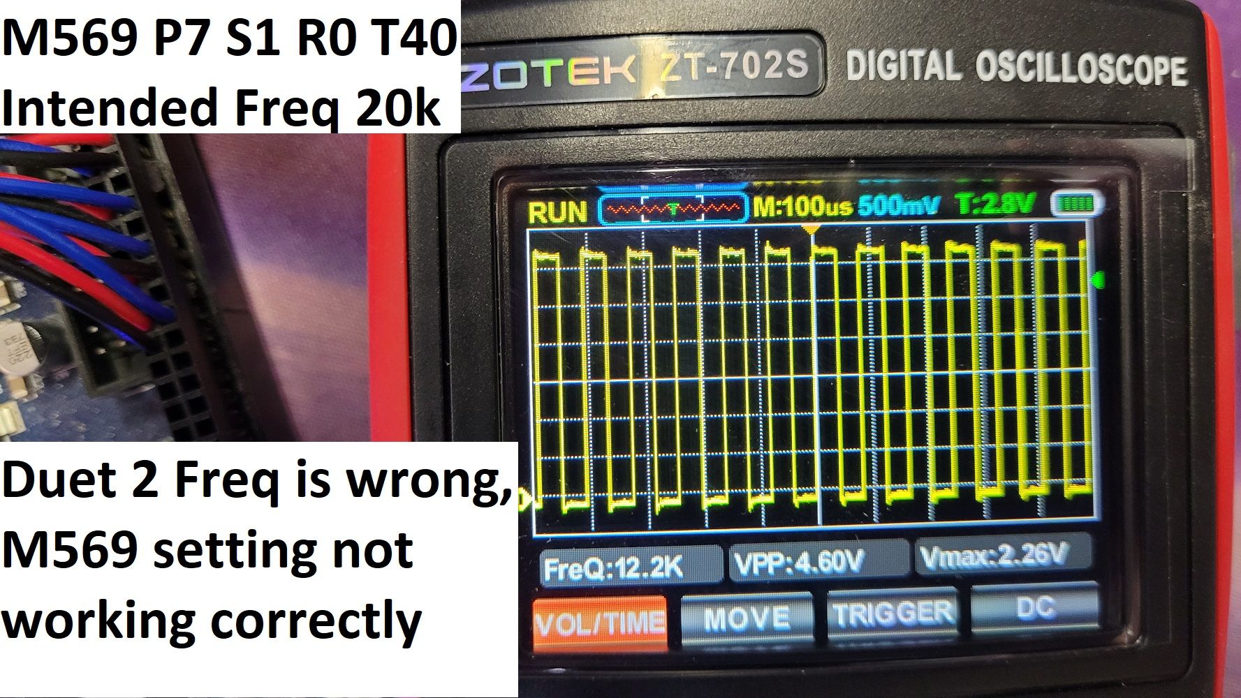
The STEP signal being generated by the Duet 2 board from the expansion slot is VERY short on the "active" time. From my understanding, PWM generation devices should have a uniform even wave length, of equal times of the peaks. Just by looking at the frequency wave, the frequency high peaks are barely able to be registered, and the low peaks are the majority of the output. I am trying to make them have equal high/low peaks.
Here is a video better describing what I am trying to have the Duet board output. A uniform symmetrical wave length, at any speed. Increasing the extruder speed (STEP signal PWM output) just makes more peaks. The low peak time is not equal to the high peak time, which is what I am trying to get.
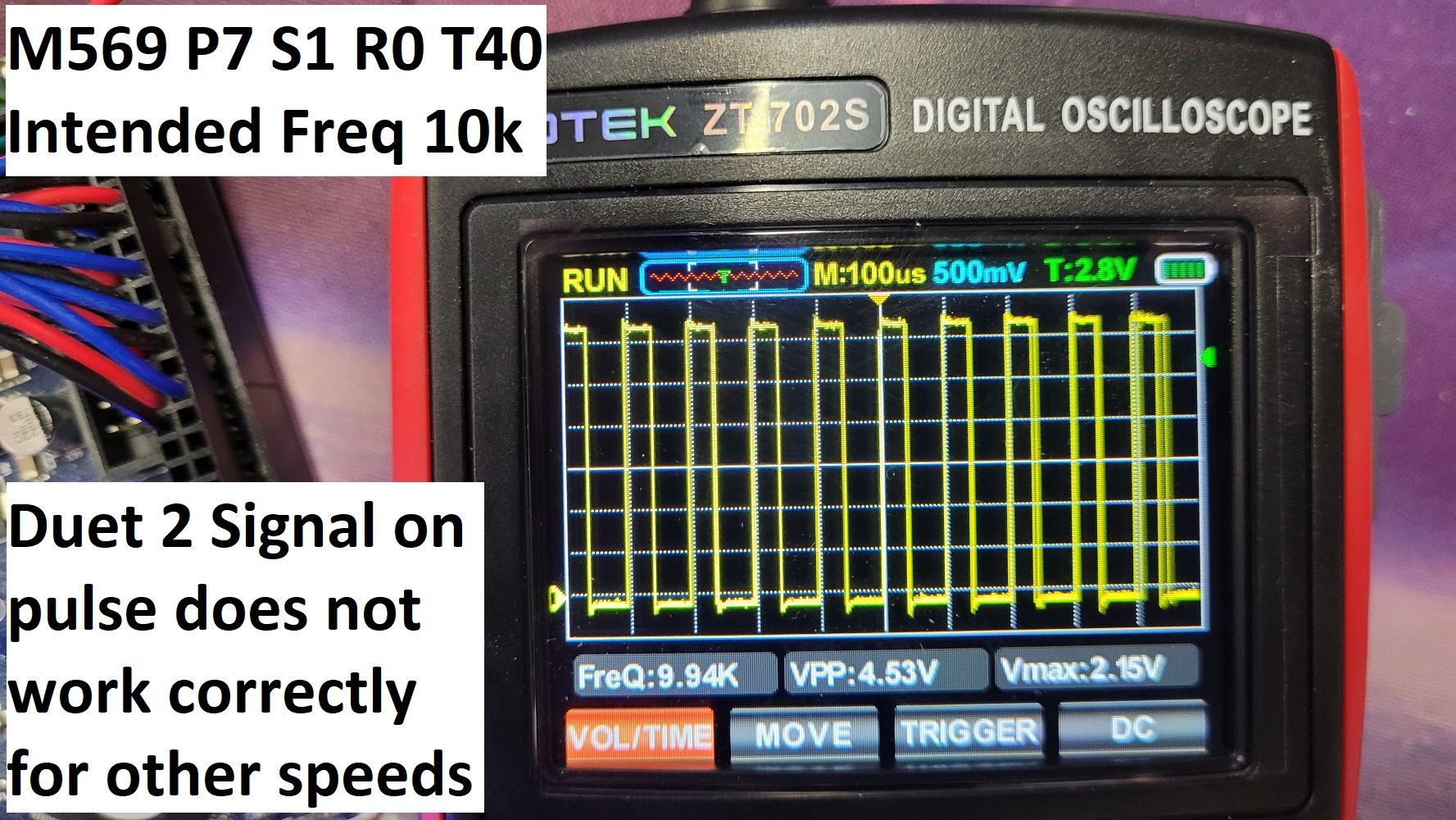
https://www.youtube.com/watch?v=UC3ZVla6fr0I have experimented with M569 P7 S1 R0 T4 in the config changing it to M569 P7 S1 R0 T40 but have not had success, as this will distort the wave form at higher output rates. Shown in pictures below.
I would also like to have a bigger Vpp (Peak-to-peak voltage) as the duet only output is ~4.5v Is there a way to increase this?
I am connecting to these pins on the control board.
Pin 2) GND
Pin 25) E6_STEPFirmware version: 3.1.1
config.g -
@3DPotter the pulses will be at least as wide as the value you specify in the T parameter. Many external drivers specify 2.5us as the minimum pulse width. You annotated one of your traces with "Duet 2 signal on pulse is VERY short" but it looks to me about right, i.e. 4us because you use T4 in your M569 command.
With T40 you are asklng for 40us high time and 40us low time, so the minimum period is 80us, which means the maximum frequency is 1/80 MHz = 12.5kHz.
There is no need to make the high and low times equal.
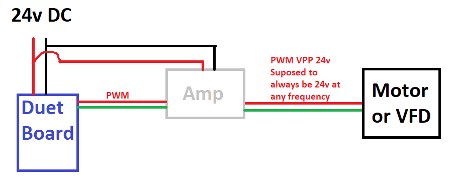
The signals on the expansion bus have 3.3V signal level and the available current is low. Most external drivers need 5V signals and more current. So you need to amplify the signals. We sell this https://www.duet3d.com/expansion_breakout to do exactly that; or you can make your own.
-
@dc42 Thank you very must for the informative information. We will be try and use an amplifier circuit.
We would use the breakout board, but we have so much stock wire cabling and harnesses that we can not switch to a different type of connector. -
@dc42 Up and running. Thank you for the information, it helped a lot. Video of it working: https://www.youtube.com/watch?v=WS5VHpAl5Vc
I do have one more question though.
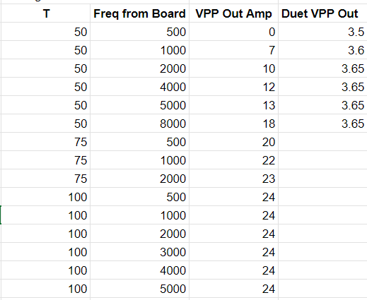
I have observed very odd measurements from the amplifying circuit output VPP when the Duet board is sending low frequencies and/or with T being low. The duet board VPP output seems constant no matter the speed/freq.
Is this from a poor quality amplifier circuit? Or does the Duet 2 board drop in available current on the PWM line when at lower frequencies? I do not believe it to be the latter, as the Duet board VPP is constant.
I assume this is due to a poor quality amplifier that requires X amount of current coming in from the PWM line from the Duet board. When the Pulse cycle length (T) is short and/or when the Frequency is small, the end result coming out of the Amplifier is small, even going to 0 VPP. When the VPP output from the amplifier is not 0, the IN/OUT PWM frequencies matches, so at least the amplifier does not distort that.
-
undefined 3DPotter has marked this topic as solved 25 Apr 2024, 17:36
-
@3DPotter it looks to me that the amplifier you are using has an output slew rate too low to handle the higher frequencies well.
