Custom 1HCL HW/FW bootloader issues
-
I made a custom circuit based on the ATSAME51G19A/1HCL. I have the mcu in circuit and have programmed it with SAME_5x v2.11 with nEDBG programmer in Microchip Studio. The chip was erased, fuses set and memory flashed as outlined in the Duet update bootloader faq. Erasing and flashing the chip went fine as verified in Studio.
Ive attached the custom board to a 6HC via CAN cycled the power several times and Im still not getting any fw update requests in DWC or seeing any other boards attached in the OM. I put a logic analyzer on the custom board CAN rx line and are getting msgs, but the tx is sitting idle/high. The circuit follows the Duet 1HCL circuit in regard to OSC, CAN, Board type and SWD so I didn't think there is anything to change in the Bootloader FW config.
I did look at the SAME_5x v2.11 config file and noticed there's a 3-bit binary board type scheme, but no analog board type scheme as the 1HCL appears to use. Anyway, I don't know if that is imperative but can't see any other reason why I can get mcu running with bootloader.
Schematic of circuit attached, any help is much appreciated
Schematic_PNP_Head_2024-12-05 (1).pdf -
So I got antsy and have some 1HCLs laying around. I pulled the mcu from the OE 1HCL and swapped it into my custom board. The CAN now works and DWC and OM is working. I noticed the Bootloader FW is different than what I was attempting to use.
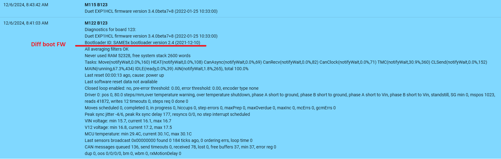
I looked up the 2.4 Bootloader and the readme states there is 1HCL specific changes in this the 2.4 ver. I never thought to look past 2.11 as it's the 'latest'. Any rate I'll work on getting my custom main fw on and see how it all goes...
Thanks guys
-
After transfering the Duet 1HCL chip onto my custom pcb I was able to boot load my custom main FW and it mostly works as expected as an CAN expansion node.
I still don't know what is going on with the bootlaoder FW not working on the blank chip. After comparing the Boot FW 2.4 to 2.11 I wasn't coming to any conclusions and I impulsively swapped the OE Deut chip out for my blank chip to see if the 2.4 Boot FW would make a difference. Still no worky
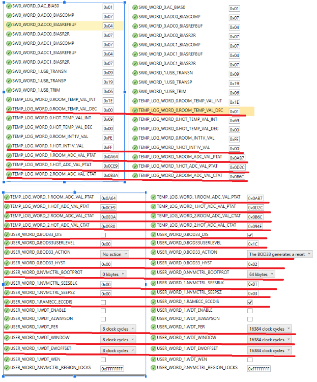
 I know the custom HW is fine and the Bootloader FW ver doesnt seem to make a difference so it must be the fuses. Before I swapped the mcus the last go I took screen shots at the fuse settings. They appear different, but I dont know what or how to interpret them or if it is imperative that they match exactly.
Heres a comparison of the blank chip fuse setting on the L and the Duet 1HCL chip on the R. the different values are underscored red. Should I just set them to match? If anyone has any advice on setting the fuses would be greatly appreciated
Thank You
-
@wayneosdias a few points:
-
From the schematic I see you are using the MAX3051 CAN transceiver. I can see a couple of potential issues with this: (1) it uses a 3.3V supply so it is likely to produce lower voltage CAN signals that the devices we use, which use a 5V supply; (2) it is not CAN-FD + BRS compatible and has a maximum bit rate of 1Mbps. This means that it won't work with future versions of RRF when we enable BRS. All Duet 3 boards are designed to work with BRS up to 4Mbps in the data phase.
-
Your drivers don't have the UART pins connected, therefore you will be unable to set the TMC2209 motor current, standstill current and other parameters from RRF. Also you don't have the DIAG pins connected so you won't be able to detect stalls - but I guess you decided you don't need to.
-
I don't think the bootloader version should matter. However, the bootloader looks at the CPU ID and the voltage on the BOARD_TYPE pin to decide what board it is, and from that which CAN port to use, which pins the CAN_RESET jumper is connected to, which pins the LEDs are connected to, what default CAN address to use, and what firmware filename to ask the main board for. See the bootloader source code for details.
HTH David
Duet WiFi hardware designer and firmware engineer
Please do not ask me for Duet support via PM or email, use the forum
http://www.escher3d.com, https://miscsolutions.wordpress.com -
-
@dc42
1, point taken and thank you for the heads up.
2, yes this is by design
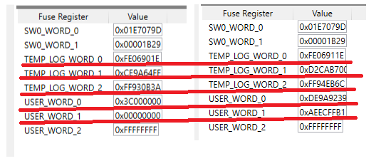
3, I presumed as much, thanks for confirming as I was having trouble following the revs to understand the relationshipI finally got a blank chip flashed and running w the bootloader and able to tie into the Duet CAN system. The issue was improper fuse setting. To fix I simply set the USER_WORD_x fuses as I read from the OE 1HCL chip;
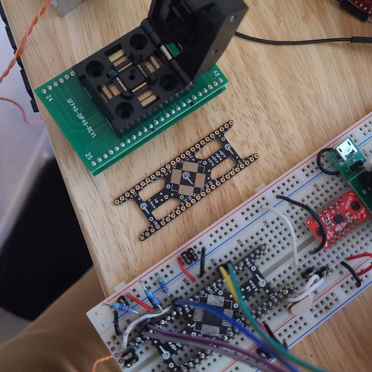
USER_WORD_0 = 0xFE9AE239 (valid)
USER_WORD_1 = 0xAEECFFB1 (valid)
USER_WORD_2 = 0xFFFFFFFF (valid)
This is good because I can now debug on the bread board which I can't do in circuit. I proceeded to order my untested circuit because I couldn't get the bootloader to work on the breadboard. I thought this was because the chip carriers got don't have a provision for the bottom solder pad. I assumed that pad was an essential ground that when missing was causing all of my problems. Fortunately not the case.
Thanks for the help David!
")
-
 undefined wayneosdias marked this topic as a question
-
undefined wayneosdias has marked this topic as solved
-
@dc42
Just to put a bow on this (Merry Xmas ). I got it all working. It took another board rev as I had a couple hw hiccups. This included to swapping the MAX3051 to the TJA1441A CAN xcvr per David's #2 note. Any rate, brand new mcu flashed the bootloader first go. I had to first set the fuses as I listed above. The default fuses had several differences, but I didn't note them.Also, all gpio, motor drivers and accelerometer are working as intended. interested. The '1HCL' is config'd as;
x3 step/dir drives
x2 med current outputs
x4 inputs, 24v tol
x1 lis3dH. I have the W on hand but just wanted to get the original circuit working first
I attached the final config with all the extraneous comments deleted in case anyone is interested.
/*
 * EXP1HCLv1_0.h
 *
 *  Created on: 3 Dec 2021
 *      Author: David
 */

#ifndef SRC_CONFIG_EXP1HCLV1_0_H_
#define SRC_CONFIG_EXP1HCLV1_0_H_

#include <Hardware/PinDescription.h>

#define BOARD_TYPE_NAME		"EXP1HCL"
#define BOOTLOADER_NAME		"SAME5x"

// General features
#define HAS_VREF_MONITOR		0
#define HAS_VOLTAGE_MONITOR		0
#define HAS_12V_MONITOR			0
#define HAS_CPU_TEMP_SENSOR		1
#define HAS_ADDRESS_SWITCHES	0
#define HAS_BUTTONS				1


// Drivers configuration
#define SUPPORT_DRIVERS			1
#define HAS_SMART_DRIVERS		0
#define HAS_STALL_DETECT		0
#define SINGLE_DRIVER			0
#define SUPPORT_SLOW_DRIVERS	0
#define SUPPORT_DELTA_MOVEMENT	0
#define DEDICATED_STEP_TIMER	1

#define ACTIVE_HIGH_STEP		1		// 1 = active high, 0 = active low
#define ACTIVE_HIGH_DIR			1		// 1 = active high, 0 = active low
#define ACTIVE_HIGH_ENABLE	 	1

#define SUPPORT_TMC51xx			0
#define SUPPORT_TMC2160			0
#define SUPPORT_TMC2660			0
#define SUPPORT_TMC22xx			0
#define SUPPORT_CLOSED_LOOP		0
#define SUPPORT_BRAKE_PWM		0

constexpr size_t NumDrivers = 3;

constexpr size_t MaxSmartDrivers = 0;

PortGroup * const StepPio = &(PORT->Group[1]);				// the PIO that all the step pins are on (port B)
constexpr Pin StepPins[NumDrivers] = { PortBPin(8), PortBPin(22), PortBPin(23) };
constexpr Pin DirectionPins[NumDrivers] = { PortBPin(9), PortAPin(24), PortAPin(27) };
constexpr Pin EnablePins[NumDrivers] = { PortBPin(2), PortAPin(20), PortAPin(25) };

#define SUPPORT_THERMISTORS		0
#define SUPPORT_SPI_SENSORS		1
#define SUPPORT_DMA_NEOPIXEL	0

#ifdef DEBUG
# define SUPPORT_I2C_SENSORS	0							// in debug mode the SERCOM is used for debugging
# define SUPPORT_LIS3DH			0
#else
# define SUPPORT_I2C_SENSORS	0
# define SUPPORT_LIS3DH			1
#endif

#define SUPPORT_DHT_SENSOR		0
#define NUM_SERIAL_PORTS		0

#define USE_MPU					0
#define USE_CACHE				1

constexpr bool UseAlternateCanPins = true;

constexpr size_t MaxPortsPerHeater = 0;

constexpr size_t NumThermistorInputs = 0;

constexpr Pin BoardTypePin = PortAPin(3);

// Diagnostic LEDs
constexpr Pin LedPins[] = { PortAPin(31), PortAPin(30) };
constexpr bool LedActiveHigh = false;

constexpr Pin VinMonitorPin = PortAPin(2);
//constexpr Pin V12MonitorPin = PortAPin(6);
//constexpr float VinDividerRatio = (100.0 + 5.1)/5.1;
//constexpr float V12DividerRatio = (60.4 + 4.7)/4.7;
//constexpr float VinMonitorVoltageRange = VinDividerRatio * 3.3;
//constexpr float V12MonitorVoltageRange = V12DividerRatio * 3.3;

constexpr Pin ButtonPins[] = { PortAPin(0) }; //Used for CAN ID reset


#if SUPPORT_I2C_SENSORS

// I2C using pins PA12,13
constexpr uint8_t I2CSercomNumber = 2;
constexpr Pin I2CSDAPin = PortAPin(12);
constexpr GpioPinFunction I2CSDAPinPeriphMode = GpioPinFunction::C;
constexpr Pin I2CSCLPin = PortAPin(13);
constexpr GpioPinFunction I2CSCLPinPeriphMode = GpioPinFunction::C;
# define I2C_HANDLER0		SERCOM2_0_Handler
# define I2C_HANDLER1		SERCOM2_1_Handler
# define I2C_HANDLER2		SERCOM2_2_Handler
# define I2C_HANDLER3		SERCOM2_3_Handler

#endif

#if SUPPORT_LIS3DH

# if SUPPORT_I2C_SENSORS

#  define ACCELEROMETER_USES_SPI			(0)				// accelerometer is connected via I2C
constexpr Pin Lis3dhInt1Pin = PortAPin(20);					// same as io1.in

# else

#  define ACCELEROMETER_USES_SPI			(1)				// accelerometer is connected via SPI
constexpr Pin Lis3dhCsPin = PortAPin(18);					// same as encoder CS pin
constexpr Pin Lis3dhInt1Pin = PortAPin(12);					// same as io1.in

# endif

#endif

// Shared SPI (used for interface to encoders, not for temperature sensors)
constexpr uint8_t SspiSercomNumber = 1;
constexpr uint32_t SspiDataInPad = 3;
constexpr Pin SSPIMosiPin = PortAPin(16);
constexpr GpioPinFunction SSPIMosiPinPeriphMode = GpioPinFunction::C;

constexpr Pin SSPISclkPin = PortAPin(17);
constexpr GpioPinFunction SSPISclkPinPeriphMode = GpioPinFunction::C;

constexpr Pin SSPIMisoPin = PortAPin(19);
constexpr GpioPinFunction SSPIMisoPinPeriphMode = GpioPinFunction::C;

// Clock generator pin for TMC2160
constexpr uint8_t ClockGenGclkNumber = 5;
constexpr Pin ClockGenPin = PortBPin(11);
constexpr GpioPinFunction ClockGenPinPeriphMode = GpioPinFunction::M;

// Table of pin functions that we are allowed to use
constexpr PinDescription PinTable[] =
{
	//	TC					TCC					ADC					SERCOM in			SERCOM out	  Exint PinName
	// Port A
	{ TcOutput::none,	TccOutput::none,	AdcInput::none,		SercomIo::none,		SercomIo::none,		0,	nullptr	    	},	// PA00 ButtonPins[0] PortAPin(0) CANRST
	{ TcOutput::tc2_1,	TccOutput::none,	AdcInput::none,		SercomIo::none,		SercomIo::none,		Nx,	nullptr			},	// PA01
	{ TcOutput::none,	TccOutput::none,	AdcInput::adc0_0,	SercomIo::none,		SercomIo::none,		Nx,	"ate.vin"		},	// PA02 VinMonitorPin PortAPin(2)
	{ TcOutput::none,	TccOutput::none,	AdcInput::adc0_1,	SercomIo::none,		SercomIo::none,		Nx, nullptr			},	// PA03 BoardTypePin PortAPin(3)
	{ TcOutput::none,	TccOutput::none,	AdcInput::adc0_4,	SercomIo::none,		SercomIo::none,		Nx,	"out1"			},	// PA04
	{ TcOutput::none,	TccOutput::none,	AdcInput::none,		SercomIo::none,		SercomIo::none,		Nx,	"out0"			},	// PA05
	{ TcOutput::none,	TccOutput::none,	AdcInput::adc0_6,	SercomIo::none,		SercomIo::none,		6,	"io0.in"		},	// PA06
	{ TcOutput::none,	TccOutput::none,	AdcInput::none,		SercomIo::none,		SercomIo::none,		Nx,	nullptr			},  // PA07
	{ TcOutput::none,	TccOutput::none,	AdcInput::none,		SercomIo::none,		SercomIo::none,		Nx,	nullptr			},	// PA08//nullptr
	{ TcOutput::none,	TccOutput::none,	AdcInput::none,		SercomIo::none,		SercomIo::none,		9,	"io1.in"		},	// PA09
	{ TcOutput::none,	TccOutput::none,	AdcInput::none,		SercomIo::none,		SercomIo::none,		10,	"io2.in"		},	// PA10
	{ TcOutput::none,	TccOutput::none,	AdcInput::none,		SercomIo::none,		SercomIo::none,		11,	"io3.in"		},	// PA11
	{ TcOutput::none,	TccOutput::tcc1_2F,	AdcInput::none,		SercomIo::none,		SercomIo::none,		12,	nullptr 		},	// PA12 Lis3dhInt1Pin = PortAPin(12);
	{ TcOutput::none,	TccOutput::none,	AdcInput::none,		SercomIo::none,		SercomIo::none,		Nx,	nullptr			},	// PA13 No IO!!
	{ TcOutput::none,	TccOutput::none,	AdcInput::none,		SercomIo::none,		SercomIo::none,		Nx,	nullptr			},	// PA14 crystal
	{ TcOutput::none,	TccOutput::none,	AdcInput::none,		SercomIo::none,		SercomIo::none,		Nx,	nullptr			},	// PA15 crystal
	{ TcOutput::none,	TccOutput::none,	AdcInput::none,		SercomIo::none,		SercomIo::none,		Nx,	nullptr			},	// PA16 SSPIMosiPin = PortAPin(16);
	{ TcOutput::none,	TccOutput::none,	AdcInput::none,		SercomIo::none,		SercomIo::none,		Nx,	nullptr			},	// PA17 SSPISclkPin = PortAPin(17);
	{ TcOutput::none,	TccOutput::none,	AdcInput::none,		SercomIo::none,		SercomIo::none,		2,	"spi.cs0" 		},	// PA18 Lis3dhCsPin = PortAPin(18);
	{ TcOutput::none,	TccOutput::none,	AdcInput::none,		SercomIo::none,		SercomIo::none,		Nx,	nullptr			},	// PA19 SSPIMisoPin = PortAPin(19);
	{ TcOutput::none,	TccOutput::none,	AdcInput::none,		SercomIo::none,		SercomIo::none,		Nx,	nullptr			},  // PA20
	{ TcOutput::none,	TccOutput::none,	AdcInput::none,		SercomIo::none,		SercomIo::none,		Nx,	nullptr			},	// PA21
	{ TcOutput::none,	TccOutput::none,	AdcInput::none,		SercomIo::none,		SercomIo::none,		Nx,	nullptr			},	// PA22 CAN0 Tx
	{ TcOutput::none,	TccOutput::none,	AdcInput::none,		SercomIo::none,		SercomIo::none,		Nx,	nullptr			},	// PA23 CAN0 Rx
	{ TcOutput::none,	TccOutput::none,	AdcInput::none,		SercomIo::none,		SercomIo::none,		Nx,	nullptr			},	// PA24
	{ TcOutput::none,	TccOutput::none,	AdcInput::none,		SercomIo::none,		SercomIo::none,		Nx,	nullptr			},	// PA25
	{ TcOutput::none,	TccOutput::none,	AdcInput::none,		SercomIo::none,		SercomIo::none,		Nx,	nullptr			},	// PA26 not on chip
	{ TcOutput::none,	TccOutput::none,	AdcInput::none,		SercomIo::none,		SercomIo::none,		Nx,	nullptr			},	// PA27
	{ TcOutput::none,	TccOutput::none,	AdcInput::none,		SercomIo::none,		SercomIo::none,		Nx,	nullptr			},	// PA28 not on chip
	{ TcOutput::none,	TccOutput::none,	AdcInput::none,		SercomIo::none,		SercomIo::none,		Nx,	nullptr			},	// PA29 not on chip
	{ TcOutput::none,	TccOutput::none,	AdcInput::none,		SercomIo::none,		SercomIo::none,		Nx,	nullptr			},	// PA30 LedPins[1] PortAPin(30)
	{ TcOutput::none,	TccOutput::none,	AdcInput::none,		SercomIo::none,		SercomIo::none,		Nx,	nullptr			},	// PA31 LedPins[0] PortAPin(31)

	// Port B
	{ TcOutput::none,	TccOutput::none,	AdcInput::none,		SercomIo::none,		SercomIo::none,		Nx,	nullptr			},	// PB00 not on chip
	{ TcOutput::none,	TccOutput::none,	AdcInput::none,		SercomIo::none,		SercomIo::none,		Nx,	nullptr			},	// PB01 not on chip
	{ TcOutput::none,	TccOutput::tcc2_2F,	AdcInput::none,		SercomIo::none,		SercomIo::sercom5d,	Nx,	nullptr			},	// PB02 EnablePins[2] PortBPin(2)
	{ TcOutput::none,	TccOutput::none,	AdcInput::adc0_15,	SercomIo::sercom5d,	SercomIo::none,		Nx,	nullptr			},	// PB03
	{ TcOutput::none,	TccOutput::none,	AdcInput::none,		SercomIo::none,		SercomIo::none,		Nx,	nullptr			},	// PB04 not on chip
	{ TcOutput::none,	TccOutput::none,	AdcInput::none,		SercomIo::none,		SercomIo::none,		Nx,	nullptr			},	// PB05 not on chip
	{ TcOutput::none,	TccOutput::none,	AdcInput::none,		SercomIo::none,		SercomIo::none,		Nx,	nullptr			},	// PB06 not on chip
	{ TcOutput::none,	TccOutput::none,	AdcInput::none,		SercomIo::none,		SercomIo::none,		Nx,	nullptr			},	// PB07 not on chip
	{ TcOutput::none,	TccOutput::none,	AdcInput::adc0_2,	SercomIo::none,		SercomIo::none,		Nx,	nullptr			},	// PB08 StepPins[2] PortBPin(8)
	{ TcOutput::none,	TccOutput::none,	AdcInput::adc0_3,	SercomIo::none,		SercomIo::none,		Nx,	nullptr			},	// PB09 DirectionPins[2] PortBPin(9)
	{ TcOutput::none,	TccOutput::tcc0_4F,	AdcInput::none,		SercomIo::none,		SercomIo::none,		Nx,	nullptr			},	// PB10
	{ TcOutput::none,	TccOutput::none,	AdcInput::none,		SercomIo::none,		SercomIo::none,		Nx,	nullptr			},	// PB11 ClockGenPin PortBPin(11);
	{ TcOutput::none,	TccOutput::none,	AdcInput::none,		SercomIo::none,		SercomIo::none,		Nx,	nullptr			},	// PB12 not on chip
	{ TcOutput::none,	TccOutput::none,	AdcInput::none,		SercomIo::none,		SercomIo::none,		Nx,	nullptr			},	// PB13 not on chip
	{ TcOutput::none,	TccOutput::none,	AdcInput::none,		SercomIo::none,		SercomIo::none,		Nx,	nullptr			},	// PB14 not on chip
	{ TcOutput::none,	TccOutput::none,	AdcInput::none,		SercomIo::none,		SercomIo::none,		Nx,	nullptr			},	// PB15 not on chip
	{ TcOutput::none,	TccOutput::none,	AdcInput::none,		SercomIo::none,		SercomIo::none,		Nx,	nullptr			},	// PB16 not on chip
	{ TcOutput::none,	TccOutput::none,	AdcInput::none,		SercomIo::none,		SercomIo::none,		Nx,	nullptr			},	// PB17 not on chip
	{ TcOutput::none,	TccOutput::none,	AdcInput::none,		SercomIo::none,		SercomIo::none,		Nx,	nullptr			},	// PB18 not on chip
	{ TcOutput::none,	TccOutput::none,	AdcInput::none,		SercomIo::none,		SercomIo::none,		Nx,	nullptr			},	// PB19 not on chip
	{ TcOutput::none,	TccOutput::none,	AdcInput::none,		SercomIo::none,		SercomIo::none,		Nx,	nullptr			},	// PB20 not on chip
	{ TcOutput::none,	TccOutput::none,	AdcInput::none,		SercomIo::none,		SercomIo::none,		Nx,	nullptr			},	// PB21 not on chip
	{ TcOutput::none,	TccOutput::none,	AdcInput::none,		SercomIo::none,		SercomIo::none,		Nx,	nullptr			},	// PB22 StepPins[1] PortBPin(22)
	{ TcOutput::none,	TccOutput::none,	AdcInput::none,		SercomIo::none,		SercomIo::none,		Nx,	nullptr			},	// PB23 StepPins[0] PortBPin(23)
};

static constexpr size_t NumPins = ARRAY_SIZE(PinTable);
static constexpr size_t NumRealPins = 32 + 24;			// 32 pins on port A (some missing), 24 on port B
static_assert(NumPins == NumRealPins);					// no virtual pins in this table

// Timer/counter used to generate step pulses and other sub-millisecond timings
TcCount32 * const StepTc = &(TC0->COUNT32);
constexpr IRQn StepTcIRQn = TC0_IRQn;
constexpr unsigned int StepTcNumber = 0;
#define STEP_TC_HANDLER			TC0_Handler

// Available UART ports
#define NUM_SERIAL_PORTS		0

// DMA channel assignments
constexpr DmaChannel DmacChanTmcTx = 0;
constexpr DmaChannel DmacChanTmcRx = 1;
constexpr DmaChannel DmacChanAdc0Rx = 2;
constexpr DmaChannel DmacChanLedTx = 3;

constexpr unsigned int NumDmaChannelsUsed = 4;			// must be at least the number of channels used, may be larger. Max 12 on the SAME5x.

constexpr DmaPriority DmacPrioTmcTx = 0;
constexpr DmaPriority DmacPrioTmcRx = 3;
constexpr DmaPriority DmacPrioAdcRx = 2;
constexpr DmaPriority DmacPrioLed = 1;

// Interrupt priorities, lower means higher priority. 0-2 can't make RTOS calls.
const NvicPriority NvicPriorityStep = 3;				// step interrupt is next highest, it can preempt most other interrupts
const NvicPriority NvicPriorityUart = 3;				// serial driver makes RTOS calls
const NvicPriority NvicPriorityI2C = 3;
const NvicPriority NvicPriorityPins = 3;				// priority for GPIO pin interrupts
const NvicPriority NvicPriorityCan = 4;
const NvicPriority NvicPriorityDmac = 5;				// priority for DMA complete interrupts
const NvicPriority NvicPriorityAdc = 5;

#endif /* SRC_CONFIG_EXP1HCLV1_0_H_ */