-
With the release of the 1.21 firmware all the missing functionality for CNC, at least what I consider mandatory, is available, so I could finally ditch the good old GRBL. The machine is a 750*750mm WorkBee, screw driven, with 3.0A steppers, home switches and limits on all axis. There are several notable differences from the standard WorkBee that influence the configuration scripts:
- home switch on the slave Y axis to allow aligning the gantry, not available by default;
- limit switches are not available so far in the default configuration, so a lot more wiring is needed;
- the Z axis is longer to allow deeper reach for a special setup.
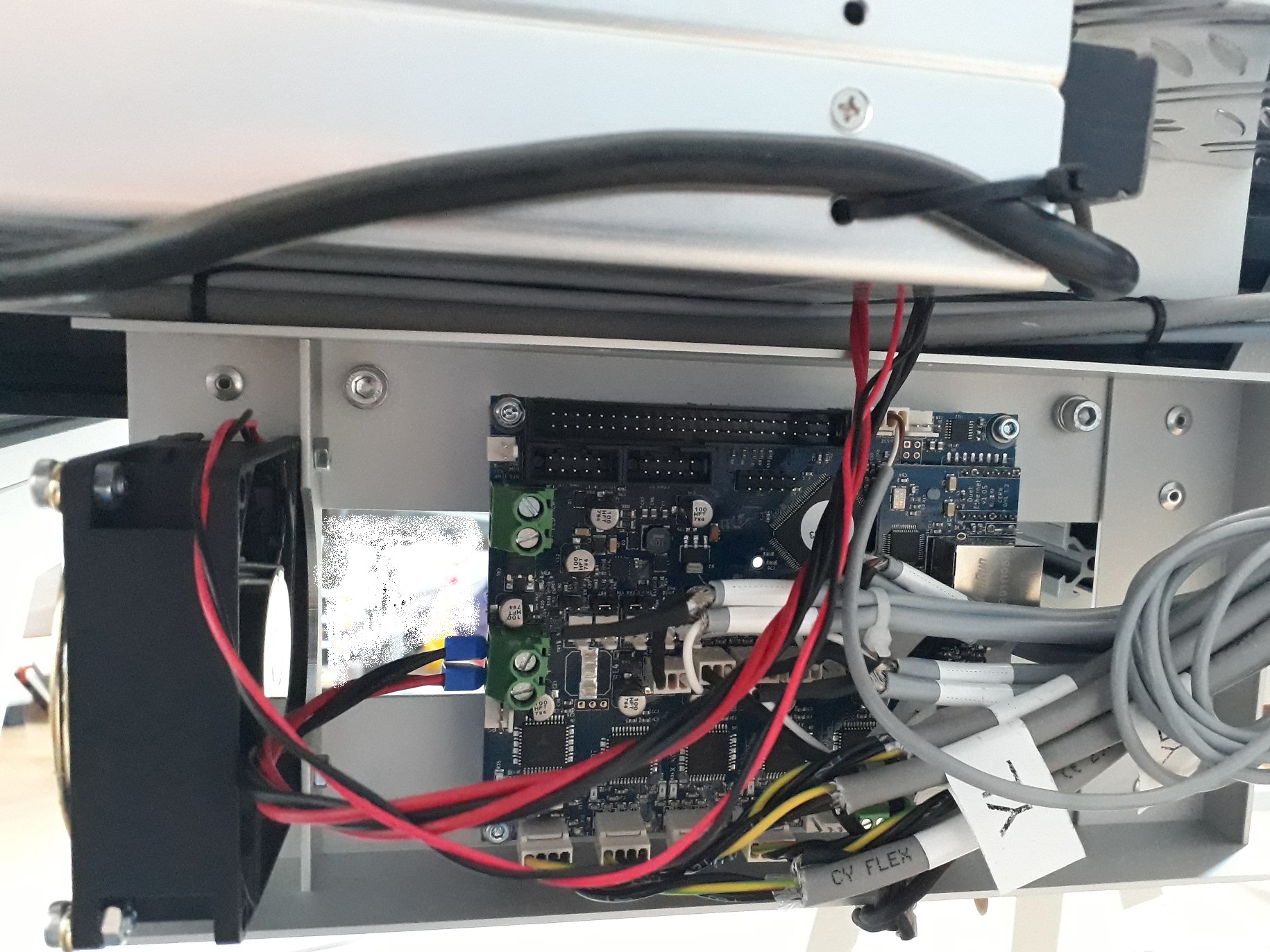
The controller is a Duet3D Ethernet, rev 1.02, updated to firmware 1.21.
For now the steppers have been limited to 2A. Tomorrow I intend to make fan mounts to insure that the drivers are properly cooled. That should allow going up to 2.4A as per the Duet3D documentation, or even more if the limit is removed at a later time.
The connections are pretty straightforward - X, left-Y and Z connected to the corresponding axis and right-Y connected to E0. Home and limit switches are NC, connected in series for each axis, the series connection being done close to the controller. All cables are shielded, with the shield connected to ground on the controller side and left floating at the stepper/switch.
There is also a tool height probe, also based on a NC switch, connected to the PROBE connector.
With the above said, this is the config.g file (produced by RRF configuration tool and then edited):
[[language]]
; General preferences
M111 S0                     ; Debugging off
M453                        ; CNC mode
G21                         ; Work in millimetres
G90                         ; Send absolute coordinates...
M83                         ; ...but relative extruder moves
M555 P2                     ; Set firmware compatibility to look like Marlin
; Automatic saving after power loss is not enabled

; Endstops
M558 P5 H5 F100 T2500      ; Set Z probe type to switch and the dive height + speeds
G31 P600 X0 Y0 Z39.55      ; Set Z probe trigger value, offset and trigger height
M557 X15:530 Y15:500 S20   ; Define mesh grid

; Drives & Axis
;
; Define axis X on drive 0, axis Y on drives 1 and 3, axis Z on drive 2 and dummy axis U on drive 9
; Show only axis X, Y and Z
M584 X0 Y1:3 Z2 U9 E4:5:6 P3
;
; Set stepper drives parameters for all the used ones
M569 P0 S1                       ; Drive 0 goes forwards
M569 P1 S0                       ; Drive 1 goes backwards
M569 P2 S1                       ; Drive 2 goes forwards
M569 P3 S0                       ; Drive 3 goes backwards
M350 X16 Y16 Z16 U16             ; Configure microstepping with interpolation
M906 X2000 Y2000 Z2000 U2000 I30 ; Set motor currents (mA) and motor idle factor in per cent
M84 S30                          ; Set idle timeout
;
; Set axis dynamic parameters
M92 X400 Y400 Z400 U400          ; Set steps per mm
M566 X400 Y400 Z12 U400          ; Set maximum instantaneous speed changes (mm/min)
M203 X2500 Y2500 Z2500 U2500     ; Set maximum speeds (mm/min)
M201 X150 Y150 Z150 U150         ; Set accelerations (mm/s^2)
;
; Set axis travel distances
M208 X0 Y0 Z0 U0 S1              ; Set axis minima
M208 X545 Y515 Z200 U515 S0      ; Set axis maxima
;
; Set axis endstops
M574 X1 Y1 Z2 U1 S1              ; Set active high endstops
M581 X Y Z U S1 T0 C0            ; Enable endstop triggers while machining

; Heaters
M140 H-1                   ; Disable heated bed

; Tools

; Network
M550 PWorkBee              ; Set machine name
M540 PBE:EF:DE:AD:FE:ED    ; Set MAC address
M552 P192.168.1.200 S1     ; Enable network and set IP address
M553 P255.255.255.0        ; Set netmask
M554 P192.168.1.254        ; Set gateway
M586 P0 S1                 ; Enable HTTP
M586 P1 S0                 ; Disable FTP
M586 P2 S0                 ; Disable Telnet

; Fans
M106 P0 S0.3 I0 F500 H-1   ; Set fan 0 value, PWM signal inversion and frequency. Thermostatic control is turned off
M106 P1 S1 I0 F500 H T45   ; Set fan 1 value, PWM signal inversion and frequency. Thermostatic control is turned on
M106 P2 S1 I0 F500 H T45   ; Set fan 2 value, PWM signal inversion and frequency. Thermostatic control is turned on

; Custom settings are not configured

; Miscellaneous
M501                       ; Load saved parameters from non-volatile memory

; Change to workplace coordinates set 1
G54
homez.g
[[language]]
M581 Z S-1 T0 C0  ; disable trigger for endstop Z
G91               ; relative mode
G1 S1 Z300 F1000  ; move Z towards the switch until it triggers
G0 Z-5            ; move Z back 5mm
G1 S1 Z10 F100    ; move Z slowly towards the switch until it triggers
G0 Z-1            ; move Z back 1mm
G90               ; back to absolute mode
G92 Z200          ; reset the Z coordinate
M581 Z S1 T0 C0   ; enable trigger for endstop Z
homex.g
[[language]]
M581 X S-1 T0 C0   ; disable trigger for endstop X
G91                ; relative positioning
G1 S1 X-1500 F1000 ; move quickly to X axis endstop and stop there (first pass)
G0 X5              ; go back a few mm
G1 S1 X-100 F100   ; move slowly to X axis endstop once more (second pass)
G0 X1              ; go back a few mm
G90                ; absolute positioning
G92 X0             ; reset the X coordinate
M581 X S1 T0 C0    ; enable trigger for endstop X
homey.g - The special line with "G0 Y0.09" is needed in my setup to fully align the gantry. No matter how much I try, there is no way to precisely place the homing switch on the slave Y axis and there might be other small mechanical differences. The offset could be applied either to Y or U axis, depending on the actual situation - the X axis must be parallel to the front beam of the machine frame and the offset can only be positive.
[[language]]
M581 Y U S-1 T0 C0        ; disable trigger for endstops Y and U
M584 Y1 U3 P4             ; separate Y and U axis for aligning them independently
G91                       ; relative positioning
G1 S1 Y-1500 U-1500 F1000 ; move quickly to Y and U axis endstops and stop there (first pass)
G0 Y5 U5                  ; go back a few mm
G1 S1 Y-10 U-10 F100      ; move slowly to Y axis endstop once more (second pass)
G0 Y0.09                  ; fully align gantry
M584 Y1:3 U9 P3           ; combine again the master and slave Y axis
G0 Y1                     ; go back a few mm
G90                       ; absolute positioning
G92 Y0                    ; reset the Y coordinate
M581 Y U S1 T0 C0         ; enable trigger for endstops Y and U
homeall.g - Partially rely on the other homing scripts in order to reduce the number of files to edit if some parameters change.
[[language]] ; first home the Z axis M98 Phomez.g ; M581 X Y U S-1 T0 C0 ; disable trigger for endstops X, Y and U M584 Y1 U3 P4 ; separate Y and U axis for aligning them independently G91 ; relative positioning G1 S1 X-550 Y-520 U-520 F1000 ; move quickly to X, Y and U axis endstops and stop there (first pass) G0 X5 Y5 U5 ; go back a few mm G1 S1 X-550 Y-520 U-520 F100 ; move slowly to X, Y and U axis endstops once more (second pass) M584 Y1:3 U9 P3 ; combine again the master and slave Y axis G0 X1 Y1 ; go back a few mm G90 ; absolute positioning G92 X0 ; reset the X coordinate M581 X Y U S1 T0 C0 ; enable trigger for endstops X, Y and U ; ; redo Y axis homing for fully aligning the gantry M98 Phomey.g -
This is very cool, thanks for the thorough report. I am looking forward to seeing some pictures.
I note your point about homing the Y. It looks like you have solved the issue I was having at MRRF with the P3 on the dual axis uncombined and recombining by explicitly putting P4 on the uncombined and P3 on the recombined axis. I should have tried that but it was busy so quite rushed. I will pass this on to 3ddistributed!
-
I already did quite a lot of machining after connecting the Duet board and more serious things came up.
(1) I tried pausing a file and I saw the machine moving to absolute 0, passing just 0.5mm above a workpiece fixture while having a rather expensive end mill in the spindle. Lesson properly learned… the content of the pause.g file must be removed! While leaving the Z movement to 5mm above the workpiece might sound interesting, if the Z axis is too close to the top there might be undesired side effects.
(2) Related to the above, leave only "G1 R1" in the resume.g file, but insure that the tool is relatively close to the workpiece and the direct path to the position where the files was paused is not going to interfere with anything.
-
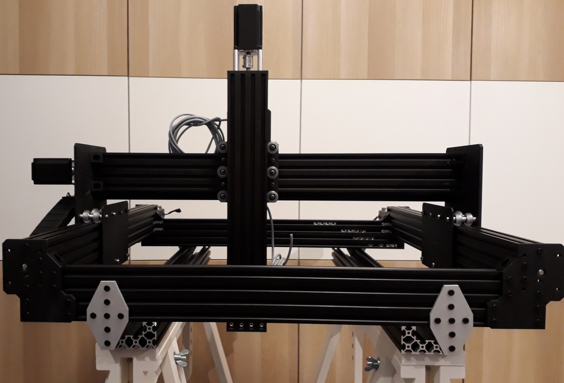
Now some pictures of the machine.
This is the whole frame, with extended Z that can visibly reach well below when machining in some tall item. The C-Beam extrusions below the front and rear beams are non-standard and are intended for extra rigidity and mechanical support for the whole machine when used as open frame.
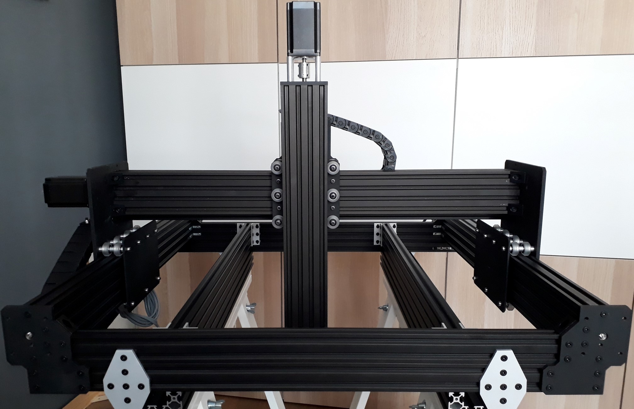
Here the machine is fully built, including drag chains.
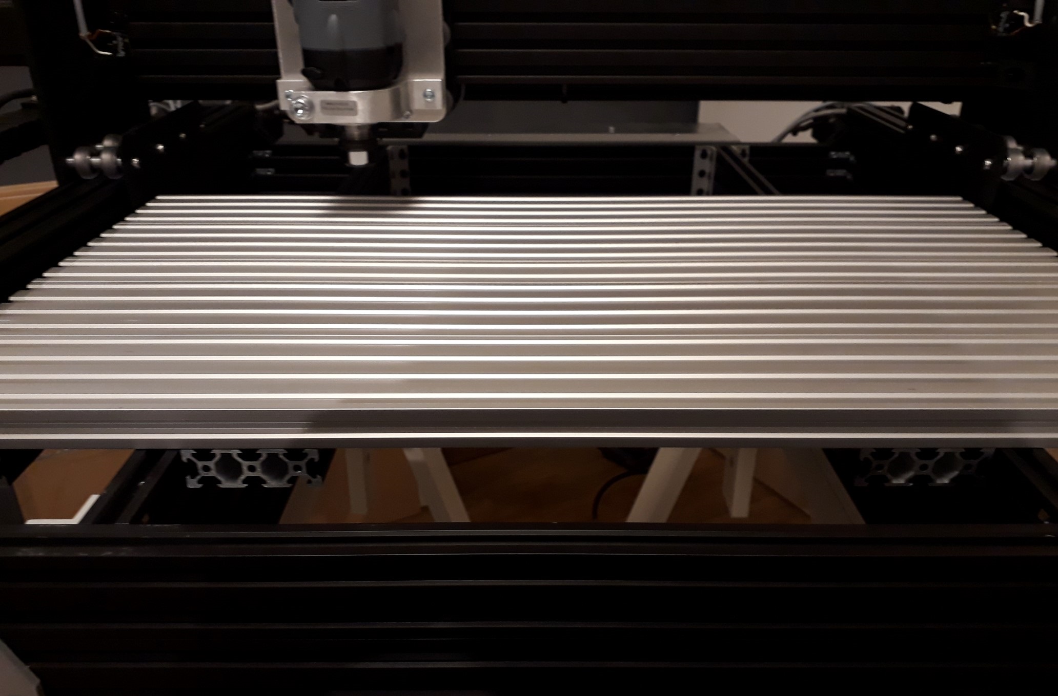
A table built from V-slot extrusions, installed in the highest position possible, for machining items from thin raw materials.
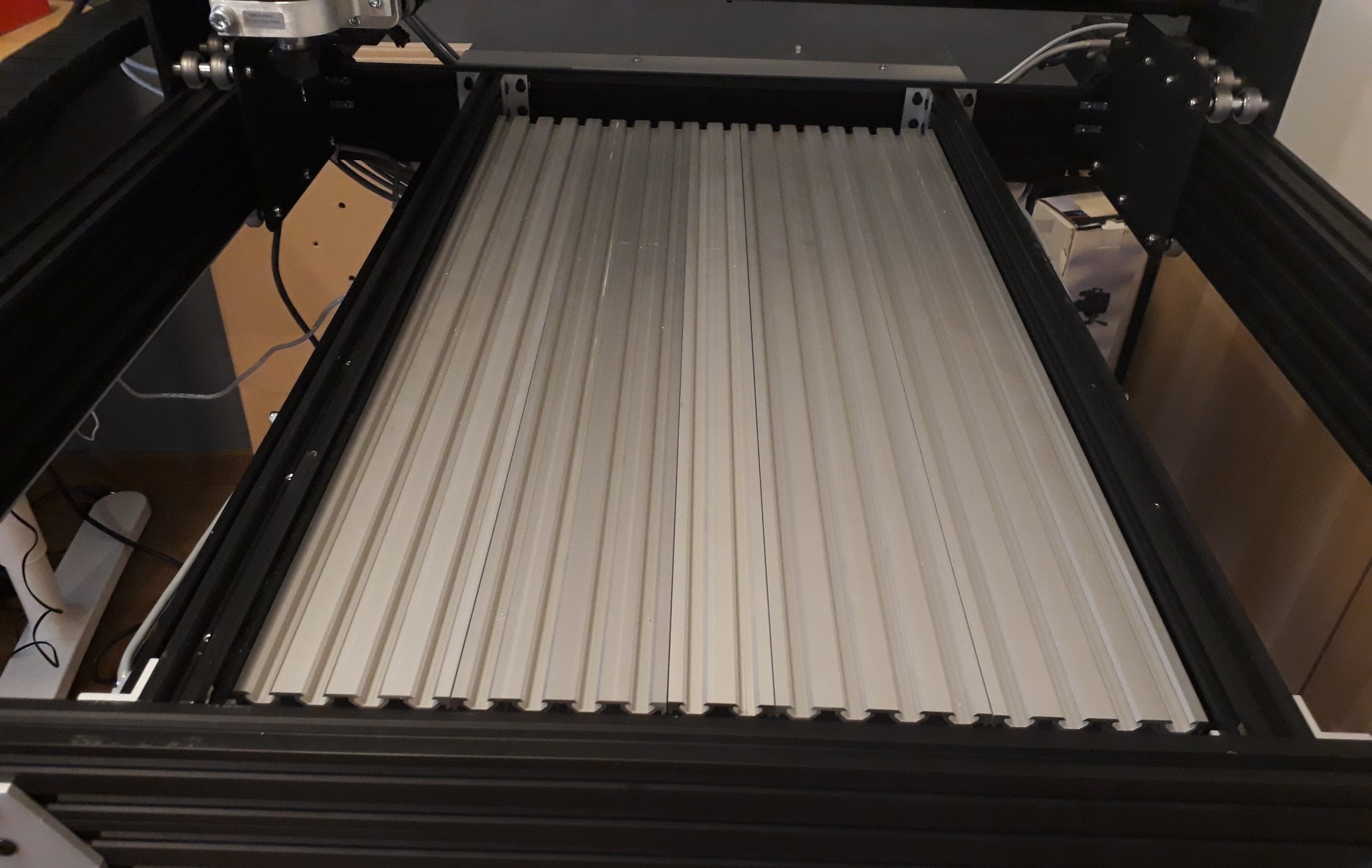
The same table installed in the central area for thicker items.
Duet3D support, including a, 80mm 24V fan. That took me about 30-40 minutes to design and mill from standard Aluminum profiles and 5 minutes to put together.
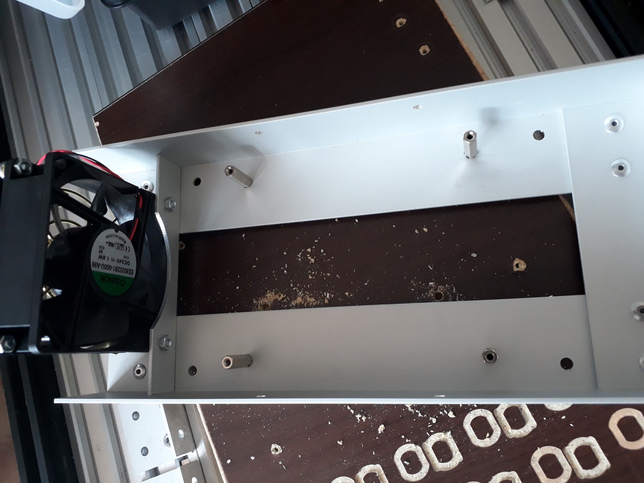
Installed Duet3D and PSU on the rear beam, under a large Aluminum sheet to prevent damage from milling residues.
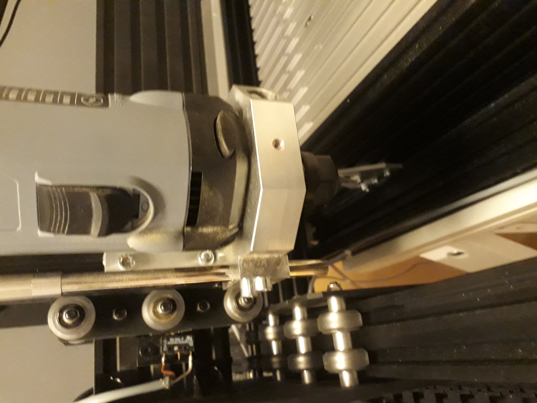
Kress spindle and USB microscope for X/Y aligning of the raw material.
-
I have created a basic page on using RepRapFirmware to control CNC machines at https://duet3d.dozuki.com/Wiki/Configuring_RepRapFirmware_for_a_CNC_machine. Those of you using Duets to control CNC machines, please feel free to edit it.
Duet WiFi hardware designer and firmware engineer
Please do not ask me for Duet support via PM or email, use the forum
http://www.escher3d.com, https://miscsolutions.wordpress.com -
Cool beans, thanks for the info, I've been planning to make a cnc router with a spare mks board, but I guess a third Duet isn't far away…
-
Thank you for posting this. im just getting setup and this is very helpful
-
After a lot of tests done with G2/G3, based on issues discovered while trying to machine a rather small Aluminum item, the maximum jerk should be limited to 300mm/min for X, Y and U. So change in config.g the line for M566 to:
M566 X300 Y300 Z12 U300
-
Thanks for the feedback!
-
OK, this is a bit amusing since I just purchased a workbee, have a duet wifi spare and a bunch of time. While waiting on it to show up here i'm spending some time creating a post processor for Bobcad/cam that'll work with the duet. Shouldn't be too terrible to make it work right.
-
@abbott_m I made one for CamBam. Actually two of them as firmware versions prior to 2.0 were not 100% compatible with GCode standards (proper or de facto ones). So if you go for firmware 2.0 you just need to avoid some GCodes that are not supported for now - like G17, G18, G19 (I have actually removed only G17 as it is safe considering that the Duet3D works only on the XY plane for now, but I left the others in place so I get an error if I configure anything wrong during CAM).
Which WorkBee have you chosen? Belt or lead screw?
-
By using latest firmware at the time of writing this, that is 2.01beta2, the maximum jerk can be safely increased to 400mm/min. Also the G2/G3 behavior, visible especially during some trochoidal machining paths as generated by CamBam, is fixed. Based on more tests that have to be done, the maximum jerk could be further increased.
-
@catalin_ro
That's interesting. Any updates?
-What kind of stepper motors are you using, Nema 23?
-Hows the duet stepper motor drivers handling the nema motors torque? -
@cncpro
Not much! The WorkBee is now changed to an 800W air cooled spindle bought on AliExpress and I have also added a 4th Axis that I install only when needed.The steppers are NEMA 23 rated for 3A, 345oz*in. They are way stronger than what the WorkBee would need.
The 3A steppers are handled very well by the Duet drivers when using a 24V PSU, much better than the GRBL+DRV8825 combo I have initially used (left over from previous CNC, until the Duet had enough CNC capabilities!). Using some higher voltage capable drivers might help getting higher RPMs but the lead screws are normally limited around 300RPM to avoid melting the Delrin nuts. With the OpenBuilds "standard" lead screws that gives 2500mm/s. For my needs that is quite enough, though I consider some times beefing up the mechanics a little bit (at 8mm thickness the lead screws a little wobbly) - but I need to find enough spare time for finding a solution.
-
@dc42 can you post current post processors on this page?
-
@adamfilip I don't know if David has any CNC mill post processor for the Duet. All I can help you with is the CamBam 1.0 one. I have used it extensively and it is working very well with firmware 2.0 and newer. As I can't upload the file (it's name is Duet3D v2.0.cbpp), here is its content:
<?xml version="1.0" encoding="utf-8"?>
<PostProcessor xmlns:xsi="http://www.w3.org/2001/XMLSchema-instance" xmlns:xsd="http://www.w3.org/2001/XMLSchema" Version="0.9.8.0">
<ToolChange />
<CutterCompOff />
<WorkplaneXY />
<VelocityModeExactStop />
<VelocityModeConstantVelocity />
<EndRewind />
<Repeat />
<SpindleCW>M3 {$s} G4 S30</SpindleCW>
<SpindleOff>G4 P0 M5</SpindleOff>
<RotaryAxis>B</RotaryAxis>
</PostProcessor> -
I asked Ryan from Ooznest about the post processor they use for Duet and they said they just use standard GRBL
-
It may be of interest that RRF 2.02RC7 supports Fanuc-style GCode in the sense that where you have a sequence multiple G0, G1, G2 or G3 commands, after the first line the subsequent lines can just specify the new coordinates (and feed rate if necessary), omitting the G command.
Duet WiFi hardware designer and firmware engineer
Please do not ask me for Duet support via PM or email, use the forum
http://www.escher3d.com, https://miscsolutions.wordpress.com -
@adamfilip GRBL might work as post processor with the latest firmware, I admit! 8 months ago that was not possible and I have added the dedicated CamBam post processor because of that.
-
With the latest rc7 firmware, fanuc postprocessor should work, I'll make a powermill post and post it here once it's done. It should be pretty easy now. It'll work with featurecam and artcam too.
If you looked for it, any cam should include a fanuc post.