Smart Effector: How Many Temp Wires?
-
Hi,
Re; the 1x8 'INPUT2' male connectror, there are four pins named,
T1, T2, T3, T4. The wiring layout drawing states the T1 & T2 are 'paired' and T3 & T4 are also paired. However, only T2 and T3 are connected to a 1x2 "TEMP" male connector located on the bottom. While it seems obvious that only 2 temperature sensors need be routed to T2 & T3 pins on INPUT2, I rather ask than learn after making the loom, that I need to wire all of the T# pins.How many of those four 'T' need be wired and routed to the DUET board?
And one last item, I presume that the 3mm plaine 'washers' should be used in conjuction with each of the mag-ball bolts? Are the washers really be required?
Thanks in advance
3mm
-
So the 4 wires are for PT100 or thermocouple I believe. PT100 can use 4 wire or 2 wires, so depending which one is what you need to connect to the bottom side. If you have a 4 wire you'd have to remove the provided connector I believe and put a 4 pin connector on. As for the 8 pin connector that has the T1-T4. If you have a PT100 and may eventually swap to 4 wire or have 4 wire you can go ahead and wire all 4 to the daughter board and remove jumpers. If you're using a standard old thermistor - as the guide says just connect 2 and 3.(If you just want to use PT100 with 2 wires the whole way also just use 2 and 3)
So really the question is what type of temperature sensor are you using?
https://duet3d.dozuki.com/Wiki/Smart_effector_and_carriage_adapters_for_delta_printer
-
@Mysta, et al,
Thanks for the nice informative reply.
MY Smart-Effector has a two pin TEMP connector soldered onto a PCB pad pattern where a four pin TEMP connector was designed to be soldered. Only the two inner pads (T2 & T3) of that 2 pin connector are physically present and those connections are routed to the 8 pin INPUT2 connector, which is the interface cable connector to the DUET controller.
The reason I asked the question is, how does a 2 pin connector attach a four wire PT100? Derived from both your answer and the documentation, it seems that my Smart-Effector was improperly assembled. A 4 pin connector that apparently was intended to attach a 4 wire sensor (T1 ~ T4) was mechanically replaced by a 2 pin connector soldered into the 4 pin connector location.
So if the temperature sensor that I can use, is constrained to only 2 wires, how many and which of the four INPUT2 T1 ~ T4 connection signals need be routed back to the DUET from the INPUT2 connector? That is the question.
The PCB artwork depicts a silk-screened assembly 'note', which states that T1/T2 and that T3/T4 are each to be paired, while physically my Smart-Effector only has the T2/T3 pins phyically connected, which are PCB routed to the 8 pin INPUT2 connector.
Which of the four marked numbered 'T' pins on the INPUT2 connector do I route back to the DUET? Also, because of this situation, need I rewire the DUET side of the cable to accomadate the seemingly funky wiring arrangement caused by the usage of a 2 pin connector instead of the intended 4 pin connector?
Re-iterating again, if a 4 pin TEMP connector had been soldered onto the PCB, I would see the validity of your nice reply. But there is a 2 pin TEMP connector soldered onto the board, not a 4 pin. The artwork has 4 pin pads but it has a 2 pin connector soldered onto it.
Maybe I'm making a mountain out of a mole-hill? However, the artwork and the schematics don't match the physical hardware I have..
Thanks in advance
3mm
There are 10 types of people: Those who understand binary and those who don't.
-
Nobody is supplying 4-wire PT100 sensors for 3D printers yet, that's why we fit a 2-pin connector. However, you can use a 2-wire PT100 and still get most of the advantages of a 4-wire one (i.e. cancel most of the wiring resistance), by running 4 wires back from the Smart Effector to the PT100 daughter board.
If you are using a thermistor and not a PT100, you need only 2 wires.
-
Oops, I missed a portion of your reply, re; the 2pin replacement of the 4pin connector. Why didn't they just mount a 4pin?
And this new board doesn't allow submitted post editing or deletion so we are all stuck with the above blah blah because I missed read your informative post.
Thanks
3mm
There are 10 types of people: Those who understand binary and those who don't.
-
Thanks for the reply. I was very confused, & add a bit of dyslexia and things can get really wobbly at times. :0
3mm
-
@3mm said in Smart Effector: How Many Temp Wires?:
Oops, I missed a portion of your reply, re; the 2pin replacement of the 4pin connector. Why didn't they just mount a 4pin?
And this new board doesn't allow submitted post editing or deletion so we are all stuck with the above blah blah because I missed read your informative post.
Thanks
3mm
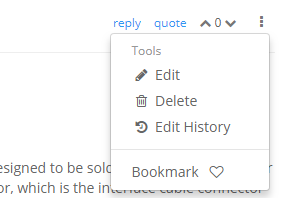
NP, the edit button is at the vertical ellipsis at the bottom right:
-
@3mm said in Smart Effector: How Many Temp Wires?:
Oops, I missed a portion of your reply, re; the 2pin replacement of the 4pin connector. Why didn't they just mount a 4pin?
Because E3D supplies their thermistors and PT100 sensors with 2-pin connectors. We didn't think users would appreciate having to remove it and crimp a 4-pin one on instead.