Simpler laser wiring without 74HCT02
-
Hi,
I bought 2.3W laser module with a TTL/PWM input. I found on wiki https://duet3d.dozuki.com/Wiki/Laser_PWM_control but I think they should be a simpler way.
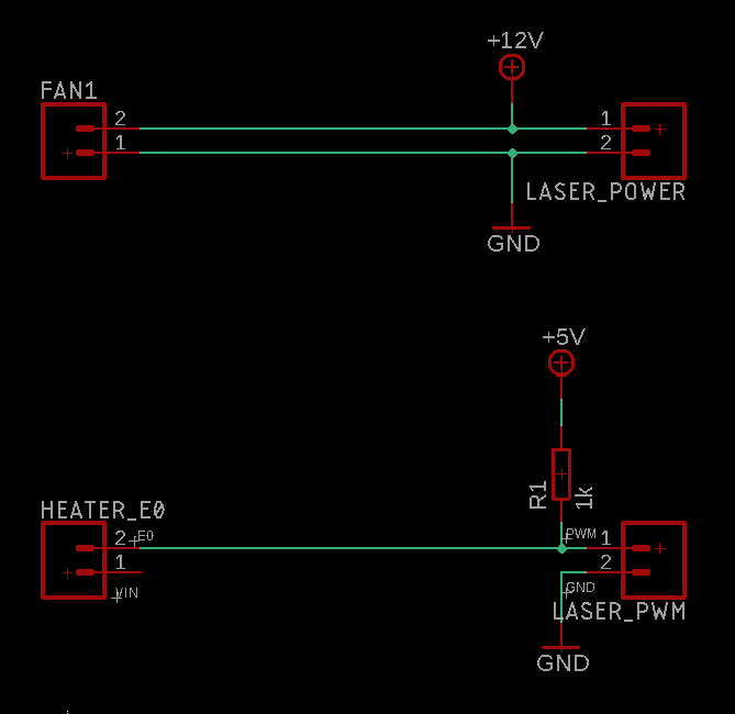
I am think about something like that:

My VIN is 24V that is why I use FAN1 output. And since FAN1 output is controlled I can control the overall power to the laser.
But maybe it would be better to use FAN2 instead of HEATER_E0? FANs outputs are low during power up? This should prevent the laser from blinking short when Duet is initializing.
What do you think about that? -
Both fan and heater outputs connect the negative side to ground to turn on the heater or the fan. So if you use a pullup resistor on them, they will default to high, hence laser on, which is not what you want. That's why we suggest the 74HCT02. We use the same technique to drive the heater mosfets.
If you have a DueX2, DueX5 or external stepper breakout board connected to your Duet, then you can use one of the servo outputs from that expansion board to drive the laser PWM input.
-
@dc42 but all my fans spins up when powering duet up? For a short pulse like ~1s. That's why I thought that fans output are low during power up.
-
The Fan 1 output on the Duet WiFi/Ethernet defaults to being on at power up, so you might be able to use that.
The other advantage of using the 74HCT02 is that in the event of a short between +3.3V and ground, it will turn the laser off.
-
@dc42 So using FAN1 for PWM and FAN2 for power would be a good solution
at power up the PWM would be zero and the laser would have any power.
And then I just set FAN2 to 100% to enable laser power.
Nice, thank you for helping. I don't wont to use 74HCT02 to avoid excessive soldering and wire mesh.
I know it have some disadvantages but anyway I am not going power up my printer and use that laser with me be in the same room. I am planning watching it over a webcam -
Using one fan output to switch power and another to switch PWM carries with it this danger. The fan outputs switch the ground side. Therefore, if the mosfet that controls PWM turns on while the mosfet that controls power is off, it will connect 12V between the V+ and PWM pins of the controller, with the ground pin essentially unconnected. This is likely to damage the controller.
-
Oh, ok I understand. Need to overthinking it again. Than you for you warning.