Laser PWM Module with Circuit Protection
-
I have ordered a PCB for the Laser PWM Module created by @keyz182.
Developed Here: https://forum.duet3d.com/topic/4632/laser-wiring
Mentioned Here: https://forum.duet3d.com/topic/6136/laser-pwm-module-v1
Write-Up Here: https://duet3d.dozuki.com/Wiki/Laser_PWM_controlAfter ordering one, I got to thinking about an addition I would like to make. Due to a polarity error I had when my laser was wired up to an Sbase, I had to go back and replace a mosfet on the laser controller that fried. IN order to prevent this and help others out I was hoping some polarity/circuit protection would be useful.
My background is in Mech Engr, so circuits always take me some work to get through. I was looking at using a mosfet to add that protection.
Reference: "How to Protect Circuits from Reversed Polarity" https://www.youtube.com/watch?v=IrB-FPcv1DcThis was what I came up with:

Can anyone provide input on the addition of the mosfet and whether or not this is a good idea or not?
Additionally, a sanity check on the selected mosfet would also be appreciated. Ive gimped my way through redesign the PCB as well and can post those changes from EasyEDA if requested.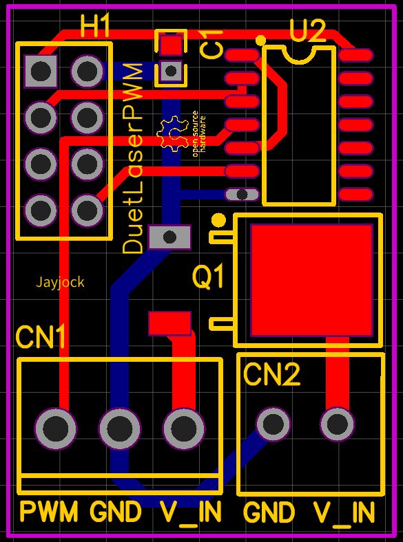
-
For that circuit to work, Q1 needs to be a P-channel MOSFET that can be turned on by 4.5V gate drive. The MOSFET you have indicated is N-channel. I didn't spot any other issues.
-
Awesome, thanks, I was just noticing that myself that the diode direction was wrong and going back to figure out the "why" N vs P channel is exactly the why.
-
Ended up fixing the mosfet to a P. Board ordered, assembled, and printed like a champ. (if anyone U.S. based is also pursuing a laser project PM me, I have extra boards now due to min order qtys. with and without mosfet design (PCB only))

-
Hi there Winged Donkey..
This is my first post so please bear with me.
I’ve just upgraded to the DUET2 WiFi board from a cnc vpro2
My old vpro2 board ran a 15w PWM laser ok. M3 M5 S255 etc.
I’m looking into following your lead / research to get my PWM laser to work.Did you solve all of your issues in getting you laser to work?
Has your PCB worked as designed?
If you still have any of the spare boards, would you be willing to post a couple to me in the UK?
I’ll cover the cost if you can help
Best regards
Phil T -
 undefined WingedDonkey referenced this topic