Duet3D Logo Duet3D
    • Tags
    • Documentation
    • Order
    • Register
    • Login
    1. Home
    2. Max3D
    • Profile
    • Following 0
    • Followers 0
    • Topics 6
    • Posts 50
    • Best 7
    • Controversial 0
    • Groups 0

    Max3D

    @Max3D

    9
    Reputation
    6
    Profile views
    50
    Posts
    0
    Followers
    0
    Following
    Joined Last Online

    Max3D Unfollow Follow

    Best posts made by Max3D

    • Huanyang VFD 2,2kw Water Cooled Spindle to D3MB6HCv1 mainboard

      Greetings,

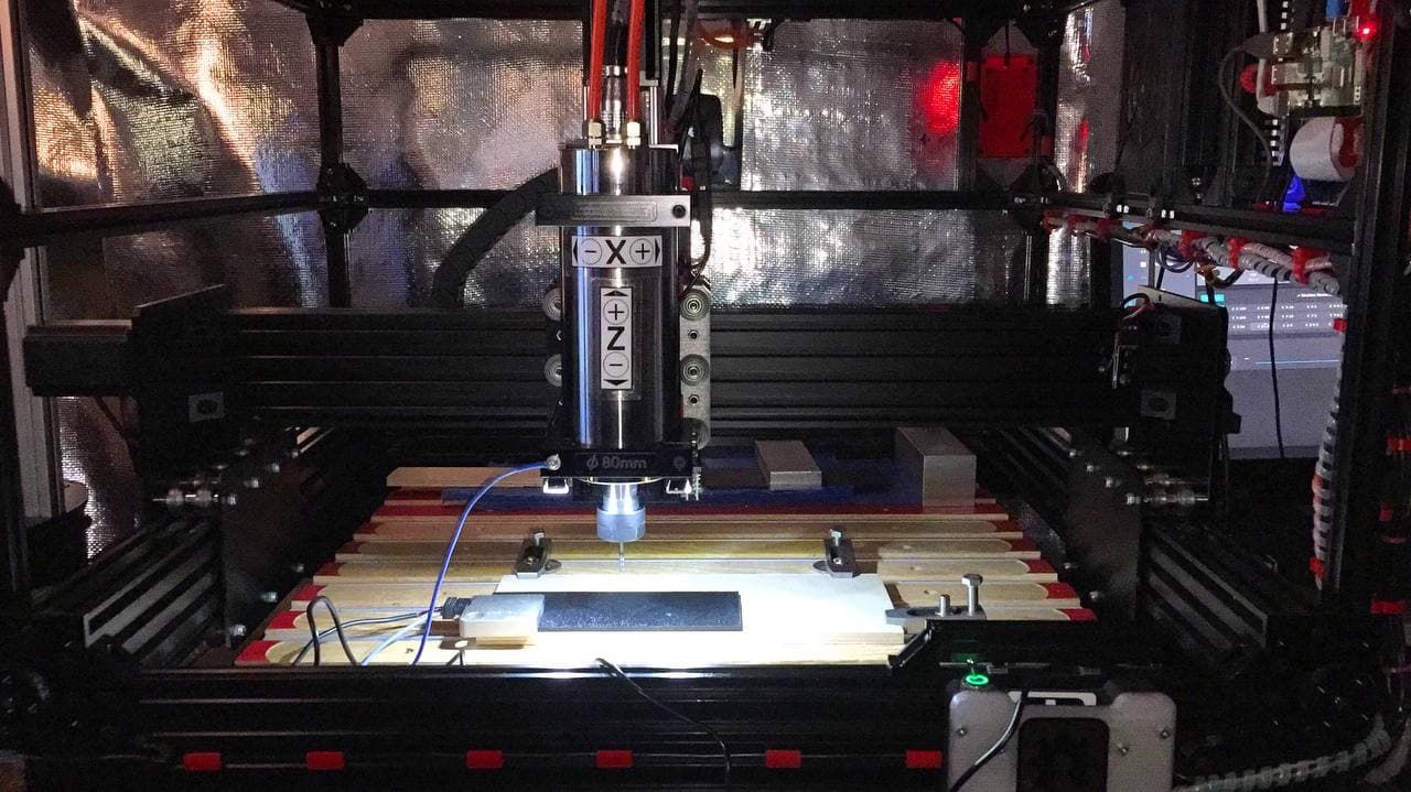
      I finished connecting my Huanyang VFD 2,2kw 110v Water Cooled Spindle to my D3MB6HCv1 mainboard. Wanted to post this info for others that wanted to do the same.

      Searched this forum and started with this post by Catalin_RO 26 Jun 2018, 13:54 - https://forum.duet3d.com/topic/4762/vfd-spindle-drive-0-10v-output/6

      I bought the module on Amazon (currently unavailable, but there are other similar modules available, make sure it is a 0-10V) KNACRO PWM to 0-10V Conversion Module Digital to Analog Module PLC Industrial Interface Conversion Module.

      Wired the module using information from an Openbuilds post here - https://openbuilds.com/threads/workbee-cnc-w-duet2-and-chinese-spindle-control.14004/

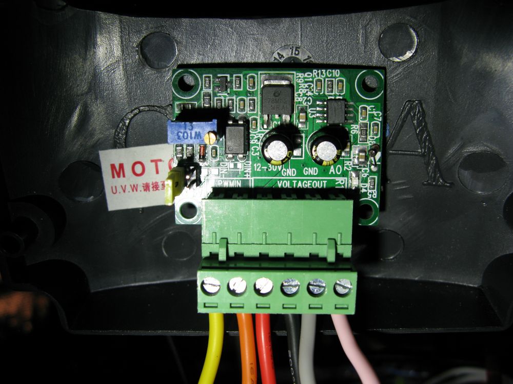
      The module needs external power and will operate at 5v and 24v. There is a white jumper on the side that can be changed for the voltage you have available. The black and red wires in the image below are from the 24v power supply that powers the mainboard.

      The orange and yellow wires are connected to the mainboard on the - 2-pin JST VH or compatible connectors OUT_1 thru OUT_3 pins normally used for extruders, heaters, and fans. I used the "OUT_1" connection. With this 2 pin connection, OUT_1 pin connects to the yellow wire and the V_FUSED connects to the orange wire.

      IMG_0149s.JPG

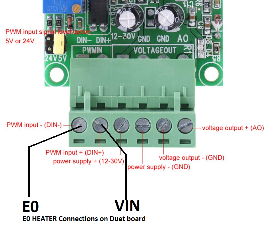
      I found this image on the Openbuilds site. I do not know if it is accurate. I could not find a schematic of the module and this image was helpful.

      PWM-to-analog-converter .png

      The grey and pink wires from the module connect to the VFD control circuit terminals at the ACM (grey) and the VI (pink) terminals. The red wire is a jumper to keep the VFD in an 'always on' state using DCM and FOR terminals, (WARNING: I do not know if this will cause some unforeseeable problem with the VFD, use at your own risk) otherwise you will need to use another module (two total) and use another pin on the mainboard to turn the spindle on when the M3 is issued. See M453 for more info: https://duet3d.dozuki.com/Wiki/Gcode#Section_M453_in_RepRapFirmware_3_0_and_3_1_x

      Next, you will need to program the VFD on the main panel. The following information was taken from: https://openbuilds.com/threads/workbee-cnc-w-duet2-and-chinese-spindle-control.14004/

      • PD001 from 0 to 1 to change spindle on/off from "operator" control to "external" control.

      • PD002 was already set to 1, which is "external" control, but until you switch the jumper, the "external" is the potentiometer on the control panel. Once you move the jumper to the left, it will use the pins.

      • PD070 from 1 to 0 to change the input voltage it's looking for from 0-5v to 0-10v. Before I changed this, the spindle speed was double what I was sending. i.e. I'd send M3 S12000 and the spindle would go to 24000RPM.

      IMG_0148.JPG

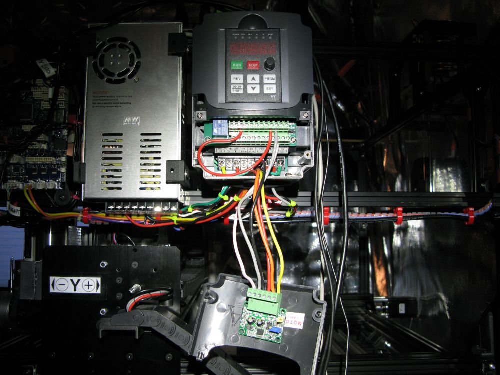
      The module is velcro'd to the inside of the hatch and out of the way when it's buttoned up.

      IMG_0150s.JPG

      The config.g needs to be reconfigured to use the "OUT_1" pin on the mainboard.

      ; Configuration file for Duet 3 (firmware version 3)
      ; executed by the firmware on start-up
      ;
      ; generated by RepRapFirmware Configuration Tool v3.1.4 on Wed Jul 29 2020 15:25:39 GMT-0700 (Pacific Daylight Time)
      
      ; General preferences
      M453			       					; CNC Mode
      G90                            			; send absolute coordinates...
      M83                            			; ...but relative extruder moves
      M550 P"Duet 3"                 			; set printer name
      
      ; Drives
      M569 P0.2 S0                   			; X 0.2 physical drive goes backwards
      M569 P0.0 S0                			; Y-R 0.0 physical drive goes backwards
      M569 P0.1 S0                   			; Y-L 0.1 physical drive goes backwards
      M569 P0.3 S1                   			; Z 0.3 physical drive goes forwards
      M584 X0.2 Y0.0:0.1 Z0.3 E0.4:0.5:0.6 	; set drive mapping
      M350 X16 Y16 Z16 U16 I1        			; configure microstepping with interpolation U=dummy Y axis
      M92 X400.00 Y400.00 Z400.00      		; set steps per mm
      M566 X900.00 Y900.00 Z12.00    			; set maximum instantaneous speed changes (mm/min)
      M203 X2000.00 Y2000.00 Z1000.00 		; set maximum speeds (mm/min)
      M201 X500.00 Y500.00 Z20.00    			; set accelerations (mm/s^2)
      M906 X3000 Y2500 Z3000 I30     			; set motor currents (mA) and motor idle factor in per cent
      M84 S30                        			; Set idle timeout
      
      ; Axis Limits
      M208 X0 Y0 Z0 S1                		; set axis minima
      M208 X500 Y375 Z60 S0          	    	; set axis maxima
      
      ; Endstops
      M574 X2 S1 P"!^io0.in"         			; configure active-high endstop for high end on X via pin !^io0.in
      M574 Y1 S1 P"!^io1.in"         			; configure active-high endstop for low end on Y via pin !^io1.in
      M574 Z2 S1 P"!^io2.in"         			; configure active-high endstop for high end on Z via pin !^io2.in
      
      ; Z-Probe
      M558 P5 c"!^io7.in" H5 F120 R1 T300     ; Z probe switch type, probe recovery 1s probe speed and travel speed
      M557 X15:215 Y15:195 S20       			; define mesh grid
      
      ; Fans
      M950 F0 C"out7" Q500           			; create fan 0 on pin out7 and set its frequency
      M106 P0 S1 H-1                 			; set fan 0 value. Thermostatic control is turned off
      M950 F1 C"out8" Q500           			; create fan 1 on pin out8 and set its frequency
      M106 P1 S1 H-1                 			; set fan 1 value. Thermostatic control is turned off
      
      ; Tools
      M563 S"XYZ-Probe" P1                    ; define XYZ Touch Probe tool 1
      M563 P0 S"Spindle"                      ; define tool 0
      G10 P0 X0 Y0 Z0                         ; set tool 0 axis offsets
      G10 P0 R0 S0                            ; set initial tool 0 active and standby temp to 0C
      
      ; Custom settings are not defined
      M564 S1 H1                              ; disable jog commands when not homed
      M501                                    ; load stored parameters
      
      ; CNC
      M453 S0 C"out1" R24000 Q100 T0          ; set to CNC mode using tool 0 pin=1 max RPM 24000 PWM frequency 100hz
      

      Lines 47-49 and line 57 need to be added. I'm not sure if lines 48 and 49 are needed concerning the G10 parameters for the M563 that defines the spindle as tool 0.

      M563 P0 S"Spindle" defines the spindel as tool 0.
      M453 S0 C"out1" R24000 Q100 T0 sets up the tool and needs to come after the M563 that defines the spindel. T0 is optional and aids the DWC in monitoring the tool.

      To test the setup, enter M3 S500 on the DWC console to turn the spindle @ 500 RPM and all should be well. Enter M5 to turn it off.

      If anyone needs help, post a reply and I'll try to help out. Otherwise, somone with more experience from Duet3D will come to your aid.

      posted in CNC
      Max3Dundefined
      Max3D
    • RE: Duet 3 MB 6HC CNC Workbee 500/750

      Just in case someone is looking for a config file and ends up here. I wanted to add that I found what I was looking for here: https://forum.duet3d.com/topic/4669/ooznest-workbee-screw-driven . The config.g from user:Catalin_RO is a good starting point for Duet 3 running a 750/750 screw driven CNC. The post also has some homing files to place in the gcode directory.

      posted in CNC
      Max3Dundefined
      Max3D
    • RE: Duet 3 D3MB6HCv1 DCS not started after upgrade.

      @chrishamm Yes, that was the case.

      The SD card has been in the Duet 3 since it was installed. I never thought to remove it because I thought it was necessary storage for the board.

      So, the SD card is to run the Duet 3 in standalone mode only and should be kept out of the Duet 3 when using an SBC?

      Many thanks to you, and everyone, for helping to resolve the problem.

      posted in CNC
      Max3Dundefined
      Max3D
    • RE: Duet 3 D3MB6HCv1 DCS not started after upgrade.

      @max3d Back in business ...

      photo_2021-04-29_13-06-24.jpg

      posted in CNC
      Max3Dundefined
      Max3D
    • RE: Openbuilds XYZ Probe Plus, G38.2 X moves in wrong direction

      @chrishamm Thank you.

      posted in CNC
      Max3Dundefined
      Max3D
    • RE: Openbuilds XYZ Probe Plus, G38.2 X moves in wrong direction

      @dc42 After reading some of the other posts regarding flashing the mainboard. I have done just about everything, including using all the USB micro cables I have, as stated in the above post. I am thinking about performing a ritual animal sacrifice to the Duet3D Gods (praise the board...) using my neighbour's Chihuahua, but before I do that, I have ordered another two USB cables with the latest USB standard. If that does not work the Chihuahua is toast ... Cables are on the way.

      Thanks for the reply,

      posted in CNC
      Max3Dundefined
      Max3D
    • RE: Openbuilds XYZ Probe Plus, G38.2 X moves in wrong direction

      @cthulhulabs Sorry for the late reply, went on Holiday... The command did not work in absolute or relative positioning. But, what did work were the commands that "crossbow" posted above. Thank you for your reply.

      posted in CNC
      Max3Dundefined
      Max3D

    Latest posts made by Max3D

    • RE: Huanyang VFD 2,2kw Water Cooled Spindle to D3MB6HCv1 mainboard

      @mdhazell Yup, you got it. The red wire connects the two terminals together.

      posted in CNC
      Max3Dundefined
      Max3D
    • RE: Huanyang VFD 2,2kw Water Cooled Spindle to D3MB6HCv1 mainboard

      @jay_s_uk Thanks for the reply. I did not have my email notification turned on so I missed your reply.

      I used a converter to protect the mainboard. I followed a suggestion from one of the administrators from another post. At the time they did not have enough information on the Huanyang VFD and the converter would be an added safety measure.

      Great addition to the post. If anyone wants to nix the converter they can use your method.

      posted in CNC
      Max3Dundefined
      Max3D
    • RE: Huanyang VFD 2,2kw Water Cooled Spindle to D3MB6HCv1 mainboard

      @mdhazell Greetings. Change PD001 from 0 to 1 to change spindle on/off from "operator" control to "external" control on the VFD control panel. You will need to power up the VFD manually before a job. I can see where this might cause some confusion because you can set the VFD up to power up and down automatically. The DCM and FOR terminals are used for that.

      Good luck ...

      posted in CNC
      Max3Dundefined
      Max3D
    • RE: Openbuilds XYZ Probe Plus, G38.2 X moves in wrong direction

      @crossbow Sorry for the late reply, went on Holiday...

      And the winner is?

      I ran the same code you suggested in 3.2.2 and it did not work. When I am testing I leave the code changes in the macro and just comment them out so I can keep track of what I tried. The difference was that I stayed with "G53 G38.2 X50 F100" and your code increased the X value by 500 and that made all of the difference. I can now zero the workpiece on the X axis with G38.2.

      Just for kicks, I lowered the X value to 100 and it works the same as the 550 value. I lowered the value to 90 and the tool moves in the wrong direction (under 90mm, about 20mm) this time and then the pinky-orange dialogue box appears with the following message: "Error: Probe was not triggered during probing move". Testing method: I do not reset the board each time, but I "HOME ALL" after each test jog to position and run macro.

      I do not know if this is just a bug for X, because I can control the direction of Y and Z without any problems in relative coords. For X the parameter value for X needs to be 100 or above ie. "G53 G38.2 X100 F100" in absolute coordinates (G90).

      Many thanks to you, and everyone, for the help.

      posted in CNC
      Max3Dundefined
      Max3D
    • RE: Openbuilds XYZ Probe Plus, G38.2 X moves in wrong direction

      @cthulhulabs Sorry for the late reply, went on Holiday... The command did not work in absolute or relative positioning. But, what did work were the commands that "crossbow" posted above. Thank you for your reply.

      posted in CNC
      Max3Dundefined
      Max3D
    • RE: Openbuilds XYZ Probe Plus, G38.2 X moves in wrong direction

      @crossbow Since I have updated to RC2, I can get G38.2 to move in a negative and positive direction on Y and Z, but X still ignores the parameter and moves to zero under the G91 relative positioning. I was able to do this with Y and Z under the stable release as well.

      posted in CNC
      Max3Dundefined
      Max3D
    • RE: Openbuilds XYZ Probe Plus, G38.2 X moves in wrong direction

      @chrishamm The problem with G38.2 persists with the update RC2 from the link you posted for the main board and the unstable update for the SBC. I will try to use the M675 command in a macro to probe the cavity in the probe plate. I think the RC2 solved a problem for user Yveske - https://forum.duet3d.com/topic/21025/duet-3-6hc-with-openbuilds-xyz-probe

      posted in CNC
      Max3Dundefined
      Max3D
    • RE: Openbuilds XYZ Probe Plus, G38.2 X moves in wrong direction

      @markz Thanks for the reply. After the update to RC2 we shall see if the G38.2 is going to behave. If not I'll give your solution a try.

      posted in CNC
      Max3Dundefined
      Max3D
    • RE: Openbuilds XYZ Probe Plus, G38.2 X moves in wrong direction

      @dc42 After multiple erase and flash attempts with various methods in powering the SBC and main board with several different cables, I finally got it to flash. I do not know what the issue was, but I don't think I want to do that again.

      I am going to reconnect everything and run the update to get it running on RC2.

      posted in CNC
      Max3Dundefined
      Max3D
    • RE: Openbuilds XYZ Probe Plus, G38.2 X moves in wrong direction

      @o_lampe You are right. I'm looking for an excuse to toast that pup. A sand flea could fart on a far away isolated beach in the Seychelles Islands on rainy night at 12:03 A.M. and that dog would hear it and bark for 31 minutes and 17 seconds. A lass the pooch has been spared. I just completed a successful erase and flash of the main board ...

      Thanks for the support and kind words.

      posted in CNC
      Max3Dundefined
      Max3D