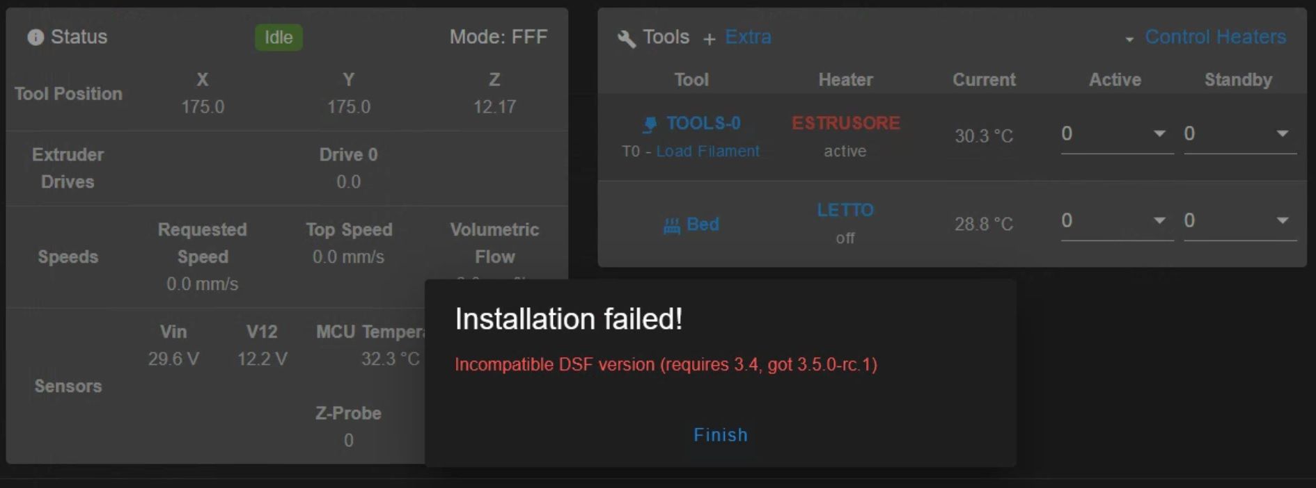
It seems to me, that after the update to 3.5.1. the LEDs controlled by the MB6HC on io.port have stopped working correctly.
The same LED strips connected to the Dotstar port continue to work properly.
in tests done with multiple LEDs (see instructions in config.g at the end of the file) the behavior of the various LEDs is very similar.
After the M150 command e.g.:
M150 E1 R255 U0 B0 W0 P50 S1 F1
M150 E1 R0 U0 B0 W255 P50 S2 F0
The first LED is light green, while the other two are correctly white. If I give the command to turn everything off e.g. M150 E1 R0 U0 B0 W0 P0 S3 F0 the first LED always remains lit green.
After turning on the printer if I do homing, the LEDs in the extruder automantically light up green. (I have no active macros).
I would like to avoid downgrading to 3.5.0 because I would have to update the mainboard, toolboard and DWC.
I would like to receive some suggestions or understand if I'm doing something wrong.
My config.g
; Voron 2.4 355x355mm Duet3 6MBHC - Toolboard 1LC - SBC with RASPBERRY PI-4 4GB and SD 64GB
; Firmware 3.5.1
; Data di aggiornamento: 02/05/2024
;
; ---------- GENERAL PREFERENCES ---------
G90                                                             ; absolute coordinates...
M83                                                             ; relative extruder moves
M669 K1                                                         ; Select CoreXY mode
M564 S1 H1                                                      ; Forbid axis movements when not homed
M575 P1 S1 B57600                                               ; enable support for Paneldue display
M290 R0 S0                                                      ; reset babystepping
;
; ---------- DRIVES MAPPINGS ----------
;
;       Rear
;	| Z1 | Z2 |
;	-----+-----
;	| Z0 | Z3 |
;	-----+-----
;	   Front
;
M584 X4 Y5 Z0:1:2:3 E121.0                                      ; set drive mapping
M569 P0 S1                                                      ; Z0 motor FL goes forwards
M569 P1 S0                                                      ; Z1 motor RL goes backwards
M569 P2 S1                                                      ; Z2 motor RR goes forwards
M569 P3 S0                                                      ; Z3 motor FR goes backwards
M569 P4 S1                                                      ; A motor goes forwards
M569 P5 S1                                                      ; B motor goes forwards
M569 P121.0 S0                                                  ; E1 motor Extruder goes backwards (scheda 1LC porta 121)
M671 X-67.5:-67.85:422.5:422.5 Y-10:443.8:443.8:-10 S15         ; Define Z belts locations (Z0=Front_Left Z1, Z2, Z3...ecc) S15=mm di correzione massima
;
; ---------- DRIVES GENERAL PARAMETERS ----------
M350 X32 Y32 Z32 E16 I1                                         ; configure microstepping with interpolation
M92 X159.94 Y159.94 Z800 E745                                   ; set steps per mm (417 afterburner, 745 stealthburner)
M84 S20                                                         ; riduzione potenza motori dopo 20sec
;
; ---------- DRIVES SPEED PARAMETERS ----------
M566 X800 Y800 Z100 E1000        	                            ; JERK (mm/min)
M203 X24000 Y24000 Z6000 E1000 		                            ; MAX SPEED (400mm/min)
M201 X7000 Y7000 Z500 E3000     	                            ; ACCELERAZIONE (mm/s^2)
M906 X2000 Y2000 Z2000 E850 I30                                 ; set motor currents (mA) and motor idle factor 30%
; IN ALTERNATIVA USARE IL FILE SOTTO:
; M98 P"/sys/print_scripts/setup_printing_med.g"                ; FILE PER STAMPA PRESTAZIONI MEDIE - FINO A 400mm/sec
; M98 P"/sys/print_scripts/setup_printing_low.g"                ; FILE PER HOMING - FINO A 250mm/sec
; M98 P"/sys/print_scripts/setup_printing_high.g"               ; FILE PER STAMPA PRESTAZIONI ELEVATE - FINO A 500mm/sec

;
; ---------- AXIS LIMITS ----------
M208 X0 Y0 Z-0.15 S1                                            ; set axis minima (S1)
M208 X350 Y350 Z320 S0                                          ; set axis maxima (S0) Portato ad H=320mm per presenza barra LED
;
; ---------- ENDSTOP SWITCH MECCANICO ---------
M574 Y2 S1 P"io1.in"                                           ; Configure enstop Y(2) posizione alta dello switch e pin !io1.in invertito
M574 X2 S1 P"io2.in"                                           ; Configure enstop x(2) posizione alta dello switch e pin !io2.in invertito
;
; ---------- SENSORE MAGNETICO FILAMENTO ---------
M591 D0 P3 C"121.io0.in" R10:190 L24.5 E10.0 S1                 ; Rotating magnet sensor for extruder drive 0 is connected to 121.io0.in on Toolboard 1LC,
; M591 D0 P0                                                    ; Disabilita controllo sensore magnetico
; ---------- Z-PROBE ----------
M558 P8 C"!121.io1.in" H10 F600 T5000                           ; set Z probe type inductive (P8),  altezza tastatura (H10), velocità tastatura mm/min (F600), velocità di spostamento mm/min (T6000) su scheda espansione 1LC porta 121
G31 P500 X0 Y24 Z1.45                                           ; set Z OFFSET, ( * PEI * ), PIU' ALTO E' Z PIU' SI AVVICINA AL LETTO
; G31 P500 X0 Y24 Z1.65                                         ; set Z OFFSET, ( * TEXTURE * ) PIU' ALTO E' Z PIU' SI AVVICINA AL LETTO
M557 X40:315 Y40:315 S55                                        ; define mesh grid (GRIGLIA maglia 6 x 6 con 55mm di spazio) EVITA I MAGNETI
;
; ----------- HO - HEATERS BED ----------
M308 S0 P"temp0" Y"thermistor" T100000 B4138 A"LETTO"           ; configure sensor 0 as thermistor on pin temp0
M950 H0 C"out1" T0                                              ; create bed heater output on out1 and map it to sensor 0
M307 H0 R0.856 K0.199:0.000 D4.53 E1.35 S1.00 B0                ; DOPO AUTOTARATURA LETTO CON (M303 H0 P1 S100) il 03/12/2023 (R=Velocità di riscaldamento °C/sec)
M140 H0                                                         ; map heated bed to heater 0
;
; ----------- H1 - HEATERS NOZZLE ----------
M308 S1 P"121.temp0" Y"thermistor" T100000 B4138 A"ESTRUSORE"   ; Configure sensor 1 as thermistor on pin temp0/121
M950 H1 C"121.out0" T1                                          ; Create nozzle heater output on out0 su scheda espansione 1LC porta 121 and map it to sensor 1
M307 H1 S0.8 B0                                                 ; H1=riscaldatore 1 S0.8=Potenza al 80% B0=BsngBang (consigliato per gli estrusori)
; M307 H1 R7.21 K0.492:0.000 D5.65 E1.35 S1.00 B0 V29.3         ; (orig. R5.331) DOPO AUTOTARATURA NOZZLE CON (M303 H1 P1 S240) il 03/12/23 HOTEND RAPIDO. (R=Velocità di riscaldamento °C/sec)
M143 H1 S275                                                    ; set temperature limit for heater 1 to 275C
;
; ---------- TOOLS ----------
M563 P0 S"TOOLS-0" D0.5 H1 F0                                   ; DEFINE TOOL 0 =>  P0=Tool 0,  S"..."=Tool name, D0.5=drive 0.5,  H1=heather 1,  F0=fan 0.
G10 P0 X0 Y0 Z0                                                 ; set tool 0 axis offsets
G10 P0 R0 S0                                                    ; set initial tool 0 active and standby temperatures to 0C
;
;	---------- FAN 0 VENTOLA RAFFR. STAMPA PWM (out4) 24v ----------
M950 F0 C"121.out2" Q500                                        ; Fan 0 su 121.out2, use PWM, using 121.out2
M106 P0 C"VENTOLA FILO" S0.0 H-1                                ; set FAN_0 name and value.
;
; ---------- FAN 1 VENTOLA HOTEND (out8) 24v ----------
M950 F1 C"121.out1" Q500                                        ; Fan 0 su 121.out2, use PWM, using 121.out2
M106 P1 C"HOTEND" H1 L0.35 X0.6 B0.3 T60:250                    ; PARAMETRICA Termostatica ( da L=35% a X=60% con temp. da 60°C a 250°C )
;
; ---------- FAN 2 VENTOLA MCU MB6HC PWM (out5) 24v ---------
M308 S2 Y"mcu-temp" A"MCU 6HC"                                  ; configure sensor 2 (S2) as thermistor for MCU
M950 F2 C"!out5+out5.tach"                                      ; Fan 2 su out5, use PWM (needs ! inverted), using out5.tach
M106 P2 C"VENTOLA MCU" L0.1 X0.8 B0.1 T26:35 H3                 ; set FAN_2 value  T26:32°C  velocità ventola L-10% X-80%
;
; ---------- FAN 3 VENTOLA PWM RASPBERRY (out4) 12v ---------
M308 S3 P"temp2" Y"thermistor" T100000 B4138 A"RASPBERRY"       ; Configura il sensore 3 (S3) come riscaldatore sul pin temp2 con nome RASPBERRY
M950 F3 C"!out4+out4.tach"                                      ; Fan 3 su out6, use PWM (needs ! inverted), using out4.tach
M106 P3 C"VENTOLA RASPBERRY" L0.1 X1.0 B0.5 T20:48 H4           ; set FAN_3 value  T20:42°C  velocità ventola L-10% X-100% B=blip time
;
; ---------- FAN 4 VENTOLA 1LC (out7) 24v ----------
M308 S4 Y"mcu-temp" P"121.dummy" A"MCU 1LC"                     ; configure sensor 4 (S4) Temp MCU 1LC
M950 F4 C"out7" Q1000                                           ; create FAN_4 on pin ou7 Toolboard and set its frequency at 1000hz
M106 P4 C"FAN 1LC MCU" H1 L0.2 X0.7 B0.3 T38:55                 ; H1=Termostatic  L=Min.Spd.  X=Max.Spd.  B=Blips Time  T=Temp Range 30-50°C
; M106 P4 S0.65									   			    ; PER ACCENDERE LA VENTOLA
; M106 P4 S0.0									   	            ; PER SPEGNERE LA VENTOLA
;
; ---------- FAN 5 VENTOLA CHASSIS (out8) 24v ----------
M950 F5 C"out8" Q1500                                           ; create FAN_5 on pin ou8 VENTOLE LATERALI DX ASPIRANTI
M106 P5 S0.00 C"CHASSIS_SX" B1								    ; ACCENDE LA VENTOLA AL 30%
;
; ---------- FAN 6 VENTOLA CHASSIS (out9) 24v ----------
M950 F6 C"out9" Q1500                                           ; create FAN_6 on pin ou9 VENTOLE LATERALI SX SOFFIANTI
M106 P6 S0.00 C"CHASSIS_DX" B1									; ACCENDE LA VENTOLA AL 30%
;
; ---------- TEMPERATURA E0 NEMA 14 SU TOOLBOARD 1LC ----------
M308 S5 P"121.temp1" Y"thermistor" T100000 B4138 A"NEMA14"      ; Configure sensor 5 (S5) as thermistor on pin temp1/121
;
; ---------- PORT 1 RELE' ACCENSIONE (io4.out) IO PORT PWM ----------
M950 P1 C"io4.out" Q500                                         ; allocate GPIO PORT.1 to io4.out at 500Hz
; M42 P1 S0.0                                                   ; Printer OFF set 0% PWM on GPIO port 1
; M42 P1 S1.0  	                                                ; Printer ON set 100% PWM on GPIO port 1
;
; ---------- ACCELEROMETRO ----------
M955 P121.0 I05                                                 ; ACCELEROMETRO SU SCHEDA 1LC ( I05 = orientamento scheda 1CL )
M593 P"ZVDDD" F36                                               ; INPUT SHAPING: Configura i parametri di riduzione risonanza
;
; ---------- TASTI FISICI SU 1LC ----------
M950 J5 C"121.button0"                                          ; Crea pin 5 su porta 121.button0 della scheda 1LC
M581 P5 T2 S1 R0                                                ; P5=pin 5 creato con M950 (J5), T2=Trigger logico a cui associare gli ingressi, S1=funziona da inattivo ad attivo, R0=attivo in ogni momento
;                                                               ; Qualsiasi numero di trigger # maggiore di 1 provoca l'esecuzione del file della macro sys/trigger2.g (T2)
M950 J6 C"121.button1"                                          ; Crea trigger n°6 su porta "121.button0"
M581 P6 T3 S1 R0                                                ; Crea pin 6 su porta 121.button1 della scheda 1LC
;
; ---------- NEOLED "0" 4 BARRE LED RGB SUPERIORI (PORTA DEDICATA DOTSTAR SU 6HC) ----------
M950 E0 C"led" T1 U155 Q3000000                                 ; Crea PIN "led" striscia LED E0 T1=RGB U160=160LED disponibili
M98 P"0:/macros/5-NEOLED ITALIA.g"                              ; Tutti i led superiori accesi al 10% (41+41+32+41=155 LED RGB)
;
; ---------- NEOLED "1" RGBW - STEALTHBURNER (PORTA IO8 OUT SU 6HC) ----------
M950 E1 C"io8.out" Q3000000 T2 U5                               ; Crea PIN "io8.out" striscia LED E1 T1=RGB T2=RGBW
;
; ---------- NEOLED "2" TEST-1 LED RGB ----------
M950 E2 C"io7.out" T1 U5 Q3000000                                 ; Crea PIN "led" striscia LED E0 T1=RGB U160=160LED disponibili
;
; ---------- NEOLED "3" TEST-2 LED RGBW ----------
M950 E3 C"io5.out" T2 U4 Q3000000                                 ; Crea PIN "led" striscia LED E0 T1=RGB U160=160LED disponibili
;
; ---------- IMPOSTA L'AUTOSALVATAGGIO IN CASO DI MANCATA ALIMENTAZIONE ----------
M911 S29.2 R29.4 P"M913 X0 Y0 G91 M83 G1 Z3 E-2 F500"           ; Autosalvataggio stampa per mancanza di corrente, sospende a 29.2v e riparte a 29.4v
;
; ---------- MISCELLANEUS ----------
M912 P0 S-1                                                     ; parametro per tarare la temperatura della MCU (-1°C)
M300 S2500 P3000                                                ; Emette suono a S=2500Hz per P=3 secondi
T0                                                              ; select first tool ACTIVE
;
My homeall.g
G91                   							            ; relative positioning
G1 H2 Z5 F2000        							            ; lift Z relative to current position
G1 H1 X350 Y350 F4000 							            ; move quickly to X or Y endstop and stop there (first pass)
G1 H1 X350            						    	           ; home X axis
G1 H1 Y350            							            ; home Y axis
G1 X-10 Y-10 F4000    							            ; go back a few mm
G1 H1 X10 F800       							            ; move slowly to X axis endstop once more (second pass)
G1 H1 Y10 F800       							            ; then move slowly to Y axis endstop once more (second pass)
G90                   							            ; absolute positioning
G1 X175 Y175 F4000    							            ; muovi al centro del piatto
G30                   							            ; home Z by probing the bed