Grid bed compensation
-
If you never home the printer after calibration then setting Z max should not change anything since the printer will be moving relatively.
But if you change the max height to be higher than what it really is, then you z=0 will be below your build surface, i.e. print head crash -
ok, finally got things worked out where I'm able to test this better.
a few notes / questions.
Notes first:
I have the auto cal set to probe at a ratios of 130, if i set the bed comp at lest say R80, everything out side that R80 is now xxmm lower than the places where i set it.let me give an example where I'm using this.
I have been making PCB's , There 6"x6". I run a auto cal that is just the bed to set end stop heights. (R130) I then run a G29 where the PCB is. (R80) in this case it works ok, but if it ever goes out side that window ( even when running manual controls) it will drop. some time up to 5mm if i probe the G29 from a new Z height…
so any how just something I think I should bring up. it might be good to set the rest of the bed out side that window to the average height of the spots probed? this may just be a one time problem for me. most will not use this like i am. however, i know i will be using smaller sections of bed types that are smaller than my full bed. ( like when testing new bed surface's)
Q. what is the max probe spots for G29? i see some where it might be 100?? could be more??
ok, here are some photos for fun, i will post a video of the CNC on the CNC thread.
~Russ
This is ALL temporary for testing...
") a work in progress. oh and yeah, the spindle, Vac, and printer are all powered by that one PS. 90A 12v ( 24V boost converters )
a work in progress. oh and yeah, the spindle, Vac, and printer are all powered by that one PS. 90A 12v ( 24V boost converters )


-
neat, a delta with a drill. It combines two of my favorite things. Do you use the delta for printing too or just for pcbs?
-
Hi Russ,
Can you post your heightmap.csv file? The height correction for points outside the probed radius should be zero, so if you are getting a 5mm difference that suggests that you have about 5mm correction within the probed radius, unless there is a bug that I haven't seen yet.
-
To make the first layer thinner, increase the z offset.
-
@CaLviNx:
Just a question to get it clear in my head.
If I want to reduce layer height i.e. Squish the layers down a bit.
Is that done by increasing or reducing the Z trigger height number?
I find it helps to think of it like this:- The trigger height is the distance from when the probe triggers to the point where the nozzle will just touch the bed. So, say for example it is 2.0mm. What are "telling" the machine is that to just touch the bed, it needs to move a further 2.0mm from the point where the probe triggers. So if your first layer needs to be 0.3mm then the machine will move in Z by 1.7mm (2.0-0.3). If you want the first layer to be squashed a bit then you have "tell" the machine that the trigger height is greater i.e 2.1 mm then it'll "think" that it has to move 1.8mm (2.1-0.3) in Z from the point where the probe triggered. Conversely if the first layer is squashed too much, then you have to "tell" the machine not to move so far after the trigger point so reduce it.
Well that works for me. Otherwise just think that less is more:)
-
I have created a wiki page on grid bed compensation at https://duet3d.com/wiki/Using_mesh_bed_compensation.
-
Hi Russ,
Can you post your heightmap.csv file? The height correction for points outside the probed radius should be zero, so if you are getting a 5mm difference that suggests that you have about 5mm correction within the probed radius, unless there is a bug that I haven't seen yet.
sorry for my amazing delays
here is 3 hight maps:
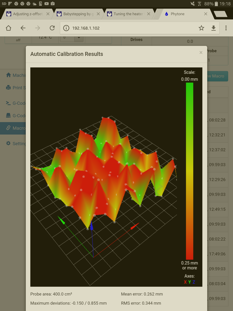
R130 with no auido cal..

RepRapFirmware height map file v1 generated at 2016-11-29 08:43
xmin,xmax,ymin,ymax,radius,spacing,xnum,ynum
-125.00,125.10,-125.00,125.10,130.00,25.00,11,11
0,0,0,0,0.734,0.760,0.759,0,0,0,0
0,0,0.756,0.738,0.760,0.780,0.813,0.808,0.881,0,0
0,0.718,0.748,0.762,0.797,0.835,0.872,0.893,0.939,1.002,0
0,0.725,0.766,0.784,0.824,0.875,0.906,0.944,1.019,1.075,0
0.699,0.753,0.802,0.825,0.878,0.947,0.962,0.994,1.077,1.113,1.196
0.742,0.788,0.847,0.888,0.937,1.029,1.056,1.072,1.141,1.138,1.242
0.778,0.851,0.916,0.974,1.030,1.082,1.146,1.177,1.191,1.233,1.265
0,0.935,0.978,1.048,1.091,1.114,1.191,1.232,1.263,1.278,0
0,1.012,1.072,1.129,1.198,1.218,1.220,1.273,1.294,1.319,0
0,0,1.162,1.210,1.256,1.306,1.291,1.285,1.268,0,0
0,0,0,0,1.354,1.383,1.389,0,0,0,0

R130 with auido cal S3

RepRapFirmware height map file v1 generated at 2016-11-29 08:55
xmin,xmax,ymin,ymax,radius,spacing,xnum,ynum
-125.00,125.10,-125.00,125.10,130.00,25.00,11,11
0,0,0,0,0.081,-0.016,-0.139,0,0,0,0
0,0,0.209,0.156,0.077,0.019,-0.079,-0.078,-0.153,0,0
0,0.263,0.191,0.147,0.082,0.038,-0.038,-0.066,-0.084,-0.094,0
0,0.248,0.148,0.128,0.073,0.012,-0.044,-0.030,-0.049,-0.023,0
0.254,0.212,0.138,0.121,0.104,0.018,-0.022,-0.009,-0.053,0.010,0.206
0.218,0.188,0.147,0.122,0.113,0.045,0.009,-0.009,-0.046,0.028,0.138
0.188,0.182,0.154,0.122,0.088,0.076,0.022,-0.021,-0.016,-0.015,0.194
0,0.150,0.144,0.094,0.059,0.043,0.021,0.003,-0.008,-0.000,0
0,0.157,0.138,0.119,0.063,-0.001,-0.008,-0.027,-0.015,0.041,0
0,0,0.141,0.118,0.093,0.022,-0.051,-0.088,-0.093,0,0
0,0,0,0,0.105,0.056,-0.023,0,0,0,0

R80 with auido cal S3

RepRapFirmware height map file v1 generated at 2016-11-29 09:11
xmin,xmax,ymin,ymax,radius,spacing,xnum,ynum
-70.00,70.10,-70.00,70.10,80.00,10.00,15,15
0,0,0,0,2.091,2.071,2.054,2.025,1.990,1.962,1.948,0,0,0,0
0,0,2.129,2.110,2.091,2.059,2.044,2.026,1.998,1.982,1.971,1.976,1.956,0,0
0,2.126,2.128,2.109,2.096,2.062,2.047,2.012,1.979,1.957,1.954,1.975,1.973,1.974,0
0,2.131,2.124,2.109,2.097,2.081,2.053,2.032,2.009,1.994,1.973,1.968,1.963,1.959,0
2.116,2.109,2.106,2.097,2.097,2.063,2.029,2.004,1.985,1.959,1.969,1.984,1.990,1.974,1.937
2.120,2.113,2.109,2.110,2.112,2.097,2.051,2.020,1.999,1.981,1.980,1.979,1.970,1.964,1.978
2.116,2.100,2.099,2.110,2.109,2.090,2.060,2.018,2.000,1.986,1.988,1.979,1.965,1.950,1.936
2.120,2.103,2.110,2.109,2.109,2.089,2.068,2.035,2.003,2.009,1.997,1.991,1.978,1.966,1.948
2.122,2.112,2.106,2.106,2.097,2.091,2.074,2.060,2.031,2.004,1.991,1.976,1.978,1.961,1.966
2.134,2.121,2.106,2.097,2.087,2.085,2.078,2.069,2.061,2.034,2.011,1.990,1.977,1.963,1.974
2.135,2.109,2.094,2.070,2.054,2.049,2.044,2.044,2.047,2.040,2.009,2.000,1.981,1.963,1.978
0,2.113,2.084,2.057,2.046,2.041,2.041,2.046,2.043,2.028,2.025,2.007,1.991,1.983,0
0,2.107,2.094,2.073,2.047,2.040,2.038,2.034,2.025,2.014,2.008,1.993,1.993,1.996,0
0,0,2.087,2.071,2.056,2.029,2.028,2.026,2.022,2.019,2.013,1.997,1.997,0,0
0,0,0,0,2.054,2.031,2.006,1.988,1.979,1.984,1.999,0,0,0,0
things sure seem odd to me…
however when cutting this space i probed it really looks good... ????
Thanks!!!!
~Russ
-
i can make a video if you want to see what i'm talking about. past the probed area. now one thing to think about is that i do a auto cal with an S3 then run the bed comp, in that process i set the probe to trigger in the " window" of the new "bed" (PCB in my case) and set everything to 0 height. so when i run the g29, it probes correctly. otherwise it will already be triggered due to the extra bed height from the approx 2.5mm PCB. however i'm only probing the PCB and nothing off that. so its as if its thinking its lower past the PCB on to the " bed"
any how let me know if you have any thoughts on this and ill try some stuff for ya if you have some ideas .
thanks!!
~Russ
-
I have created a wiki page on grid bed compensation at https://duet3d.com/wiki/Using_mesh_bed_compensation.
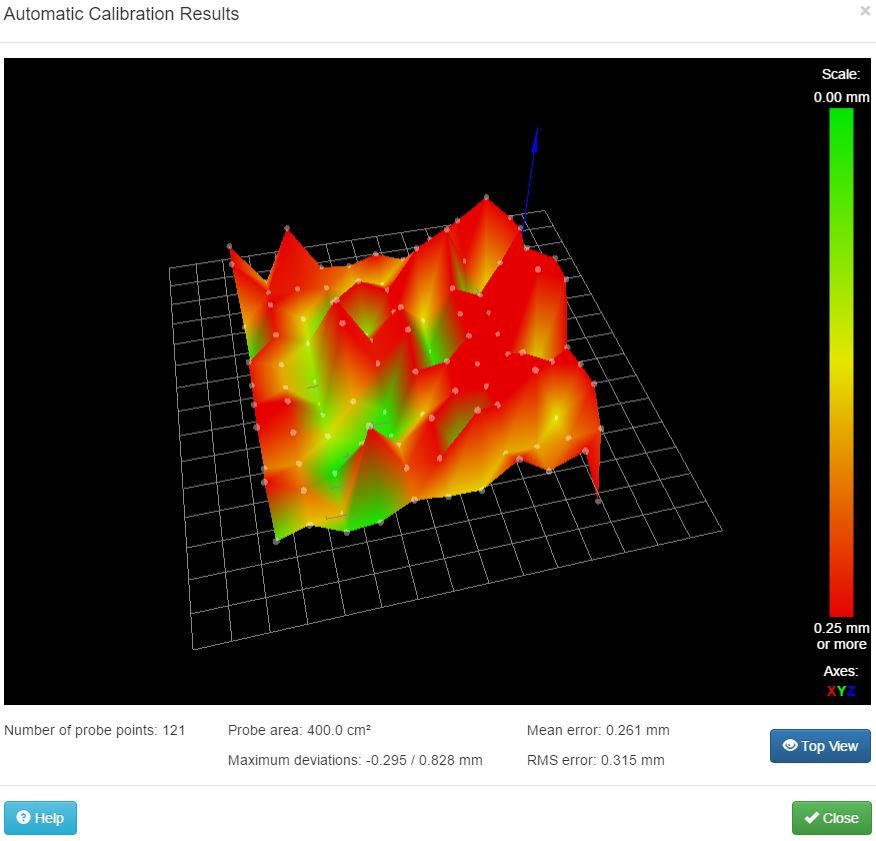
thanks for create yet another great write-up/tutorial. It was very easy to follow and understand. I do have a question/request. Can you briefly explain how to interpret the results? What's good vs bad? How can you tell if the results of the compensations will be beneficial?
my results are below using the standard setttings
Thanks
[[language]] RepRapFirmware height map file v1 generated at 2017-00-08 01:21, mean error 0.03, deviation 0.15 xmin,xmax,ymin,ymax,radius,spacing,xnum,ynum -120.00,120.10,-120.00,120.10,130.00,20.00,13,13 0, 0, 0, 0, 0.071, -0.208, -0.136, -0.057, -0.009, 0, 0, 0, 0 0, 0, 0.308, 0.122, 0.027, -0.030, -0.021, -0.070, -0.121, -0.135, 0.198, 0, 0 0, 0.174, -0.101, -0.150, -0.152, -0.108, 0.008, 0.065, 0.108, 0.200, 0.314, 0.459, 0 0, 0.345, 0.212, 0.119, 0.084, 0.017, 0.026, -0.017, -0.028, -0.067, -0.029, 0.154, 0 0.251, -0.130, -0.146, -0.135, -0.097, -0.086, 0.025, 0.081, 0.156, 0.259, 0.372, 0.467, 0.533 0.363, 0.217, 0.119, 0.038, -0.010, -0.056, -0.059, -0.057, -0.059, -0.049, -0.012, 0.007, 0.156 -0.057, -0.206, -0.173, -0.142, -0.106, -0.059, -0.032, 0.042, 0.121, 0.185, 0.261, 0.327, 0.347 0.070, 0.054, 0.030, -0.007, -0.029, -0.075, -0.077, -0.067, -0.057, -0.067, -0.083, -0.083, 0.093 -0.171, -0.235, -0.193, -0.141, -0.085, -0.041, 0.017, 0.056, 0.119, 0.168, 0.203, 0.186, 0.157 0, -0.134, -0.103, -0.105, -0.097, -0.046, -0.000, -0.017, -0.060, -0.074, -0.106, -0.036, 0 0, -0.172, -0.224, -0.140, -0.058, 0.038, 0.114, 0.141, 0.119, 0.121, 0.082, -0.011, 0 0, 0, -0.114, -0.041, 0.028, 0.001, -0.008, 0.048, 0.047, -0.049, 0.054, 0, 0 0, 0, 0, 0, 0.121, 0.100, 0.143, 0.175, 0.147, 0, 0, 0, 0 -
G29 bed compensation will benefit you if:
1. The height map you get is repeatable if you run G29 more than once. You can use the P parameter to specify a filename for the height map so that you can have more than one.
and
2. Your Z=0 height setting is generally more accurate all over the bed with compensation enabled than without. So use the paper test to check how accurate Z=0 is at various points on the bed, with and without compensation enabled.
In some areas, your height map varies faster than I would expect, for example 0.363 followed by -0.057 on the left hand side. If this only happens at the edges of the print area, it could mean that you have reached the limit of movement of the joints.
-
G29
In some areas, your height map varies faster than I would expect, for example 0.363 followed by -0.057 on the left hand side. If this only happens at the edges of the print area, it could mean that you have reached the limit of movement of the joints.
I have seen this for sure. took me a while to figure it out. its small but its there.
~Russ
-
I have created a wiki page on grid bed compensation at https://duet3d.com/wiki/Using_mesh_bed_compensation.
In Using mesh bed compensation > Checking the trigger height > "3. Send M208 Z-3 to temporarily allow Z moves down to Z=-3mm."
I believe it should read "Send M208 Z-3 S1 …", otherwise 'Z-3' becomes the new Z-axis max travel limit. -
Thank you, I have corrected it.
-
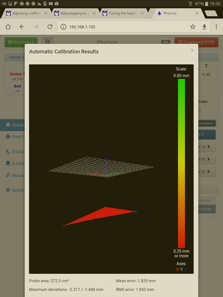
I'm loving the web interface, but I was annoyed with swiss alps as the reading from the bed mapping. So i purchased some new ecocast tooling plate from the aluminium warehouse (which looks flat to me) and re-ran the bed mapping. I'm using DC42's IR sensor, and its straight onto the top of the aluminium cast tooling plate.
I still get the Swiss Alps - can anyone suggest what is going on?
I get a similar trace from both sides of two sheets of ecocast
Also when running auto bed compensation from the web interface, it seems the bed is well below the surface - yet i've calibrated the system according to the grid bed wiki guide. I'm working on the angle, as it would seem something is not flat on my printer bed.
Any help gratefully received….
-
and here is the bed file, of another run:
RepRapFirmware height map file v1, mean error -0.68, deviation 0.24
xmin,xmax,ymin,ymax,radius,spacing,xnum,ynum
40.00,240.00,20.00,220.00,-1.00,20.00,11,11
-0.209, -0.239, -0.680, -0.433, -0.411, -0.539, -0.924, -0.377, -0.448, -0.751, -1.148
-0.263, -0.801, -0.364, -0.404, -0.672, -0.803, -0.520, -0.655, -1.017, -0.631, -0.571
-0.286, -0.202, -0.485, -0.892, -0.488, -0.396, -0.830, -0.675, -0.552, -0.616, -1.123
-0.522, -0.810, -0.453, -0.478, -0.921, -0.594, -0.517, -0.916, -1.042, -0.658, -0.584
-0.421, -0.510, -0.988, -0.500, -0.379, -0.751, -0.860, -0.744, -0.505, -0.990, -0.707
-0.549, -0.470, -0.658, -1.057, -0.542, -0.473, -0.776, -0.892, -0.621, -0.562, -1.025
-0.995, -0.537, -0.493, -0.722, -0.990, -0.648, -0.633, -0.941, -0.722, -0.522, -0.719
-0.946, -0.717, -0.534, -0.768, -1.101, -0.643, -0.547, -0.648, -0.968, -0.539, -0.547
-1.020, -0.739, -0.616, -0.685, -1.163, -0.589, -0.429, -0.732, -0.985, -0.534, -0.451
-1.148, -0.685, -0.574, -0.756, -1.081, -0.677, -0.490, -1.429, -0.921, -0.601, -0.547
-0.906, -0.670, -0.677, -1.096, -0.628, -0.485, -0.751, -1.076, -0.525, -0.389, -0.732 -
On DC42s blog write up https://miscsolutions.wordpress.com/mini-height-sensor-board/, he talks about bed surfaces and states " Bright aluminium: not suitable unless the sensor is modified to reduce its sensitivity, because the strong reflection will saturate the sensor." You state that you are probing straight onto the top of the aluminium tooling plate so maybe that's where things are going a bit haywire. Maybe paint the plate matt black? - I use stove paint and bake it in the oven. HTH
Ian -
I get a similar trace when doing it on printbite, which is why I got some new plate. I'll find some black card and insert between the printbite and plate to see if that helps first.
Thanks for the tip.
-
I get a similar trace when doing it on printbite, which is why I got some new plate. I'll find some black card and insert between the printbite and plate to see if that helps first.
Thanks for the tip.
DC does recommend painting the plate black if you are using glass. I know printbite isn't glass but it's still fairly transparent so maybe the same applies? Black card has to be worth a try. Stove paint is a bit expensive so I can understand that you'd want to be sure it will work. Ian
-
Couldn't find any card, so thought running the grid probe in the dark….
Amazes me it works, but oh well... ordered some paint, for sake of £7, has to be worth a try.....