Grid bed compensation
-
I have created a wiki page on grid bed compensation at https://duet3d.com/wiki/Using_mesh_bed_compensation.
thanks for create yet another great write-up/tutorial. It was very easy to follow and understand. I do have a question/request. Can you briefly explain how to interpret the results? What's good vs bad? How can you tell if the results of the compensations will be beneficial?
my results are below using the standard setttings
Thanks
[[language]] RepRapFirmware height map file v1 generated at 2017-00-08 01:21, mean error 0.03, deviation 0.15 xmin,xmax,ymin,ymax,radius,spacing,xnum,ynum -120.00,120.10,-120.00,120.10,130.00,20.00,13,13 0, 0, 0, 0, 0.071, -0.208, -0.136, -0.057, -0.009, 0, 0, 0, 0 0, 0, 0.308, 0.122, 0.027, -0.030, -0.021, -0.070, -0.121, -0.135, 0.198, 0, 0 0, 0.174, -0.101, -0.150, -0.152, -0.108, 0.008, 0.065, 0.108, 0.200, 0.314, 0.459, 0 0, 0.345, 0.212, 0.119, 0.084, 0.017, 0.026, -0.017, -0.028, -0.067, -0.029, 0.154, 0 0.251, -0.130, -0.146, -0.135, -0.097, -0.086, 0.025, 0.081, 0.156, 0.259, 0.372, 0.467, 0.533 0.363, 0.217, 0.119, 0.038, -0.010, -0.056, -0.059, -0.057, -0.059, -0.049, -0.012, 0.007, 0.156 -0.057, -0.206, -0.173, -0.142, -0.106, -0.059, -0.032, 0.042, 0.121, 0.185, 0.261, 0.327, 0.347 0.070, 0.054, 0.030, -0.007, -0.029, -0.075, -0.077, -0.067, -0.057, -0.067, -0.083, -0.083, 0.093 -0.171, -0.235, -0.193, -0.141, -0.085, -0.041, 0.017, 0.056, 0.119, 0.168, 0.203, 0.186, 0.157 0, -0.134, -0.103, -0.105, -0.097, -0.046, -0.000, -0.017, -0.060, -0.074, -0.106, -0.036, 0 0, -0.172, -0.224, -0.140, -0.058, 0.038, 0.114, 0.141, 0.119, 0.121, 0.082, -0.011, 0 0, 0, -0.114, -0.041, 0.028, 0.001, -0.008, 0.048, 0.047, -0.049, 0.054, 0, 0 0, 0, 0, 0, 0.121, 0.100, 0.143, 0.175, 0.147, 0, 0, 0, 0 -
G29 bed compensation will benefit you if:
1. The height map you get is repeatable if you run G29 more than once. You can use the P parameter to specify a filename for the height map so that you can have more than one.
and
2. Your Z=0 height setting is generally more accurate all over the bed with compensation enabled than without. So use the paper test to check how accurate Z=0 is at various points on the bed, with and without compensation enabled.
In some areas, your height map varies faster than I would expect, for example 0.363 followed by -0.057 on the left hand side. If this only happens at the edges of the print area, it could mean that you have reached the limit of movement of the joints.
-
G29
In some areas, your height map varies faster than I would expect, for example 0.363 followed by -0.057 on the left hand side. If this only happens at the edges of the print area, it could mean that you have reached the limit of movement of the joints.
I have seen this for sure. took me a while to figure it out. its small but its there.
~Russ
-
I have created a wiki page on grid bed compensation at https://duet3d.com/wiki/Using_mesh_bed_compensation.
In Using mesh bed compensation > Checking the trigger height > "3. Send M208 Z-3 to temporarily allow Z moves down to Z=-3mm."
I believe it should read "Send M208 Z-3 S1 …", otherwise 'Z-3' becomes the new Z-axis max travel limit. -
Thank you, I have corrected it.
-
I'm loving the web interface, but I was annoyed with swiss alps as the reading from the bed mapping. So i purchased some new ecocast tooling plate from the aluminium warehouse (which looks flat to me) and re-ran the bed mapping. I'm using DC42's IR sensor, and its straight onto the top of the aluminium cast tooling plate.
I still get the Swiss Alps - can anyone suggest what is going on?
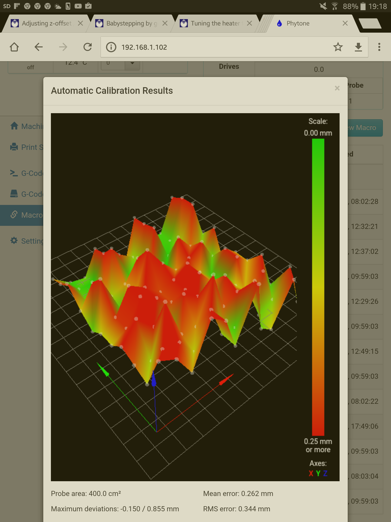
I get a similar trace from both sides of two sheets of ecocast
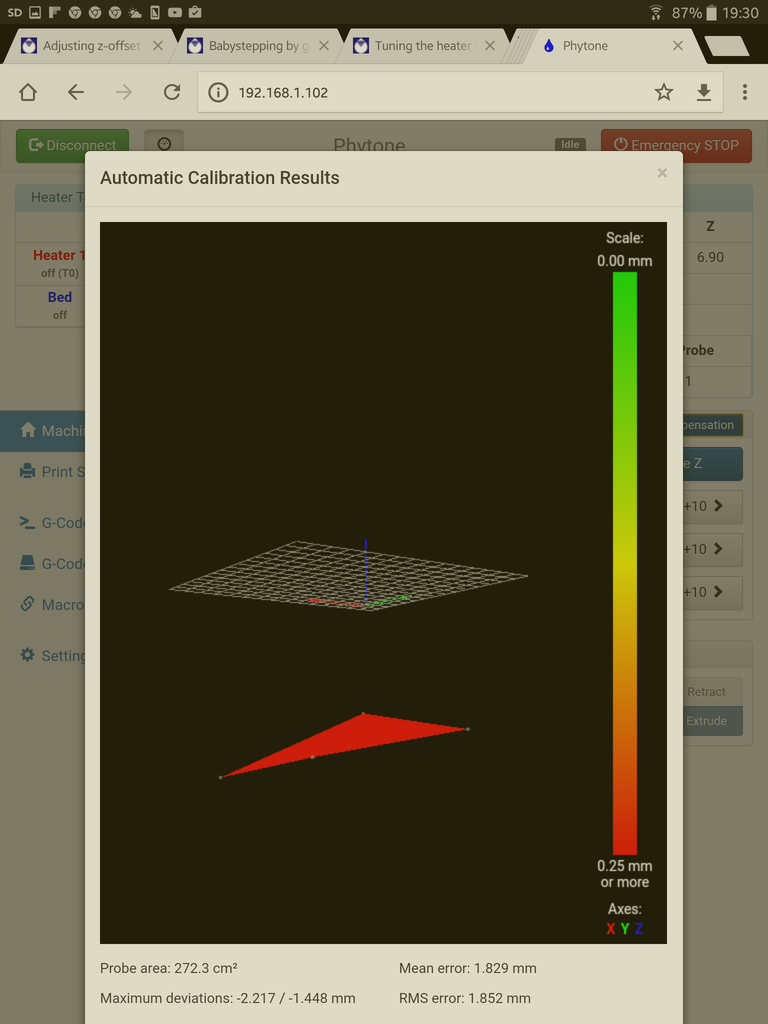
Also when running auto bed compensation from the web interface, it seems the bed is well below the surface - yet i've calibrated the system according to the grid bed wiki guide. I'm working on the angle, as it would seem something is not flat on my printer bed.
Any help gratefully received….
-
and here is the bed file, of another run:
RepRapFirmware height map file v1, mean error -0.68, deviation 0.24
xmin,xmax,ymin,ymax,radius,spacing,xnum,ynum
40.00,240.00,20.00,220.00,-1.00,20.00,11,11
-0.209, -0.239, -0.680, -0.433, -0.411, -0.539, -0.924, -0.377, -0.448, -0.751, -1.148
-0.263, -0.801, -0.364, -0.404, -0.672, -0.803, -0.520, -0.655, -1.017, -0.631, -0.571
-0.286, -0.202, -0.485, -0.892, -0.488, -0.396, -0.830, -0.675, -0.552, -0.616, -1.123
-0.522, -0.810, -0.453, -0.478, -0.921, -0.594, -0.517, -0.916, -1.042, -0.658, -0.584
-0.421, -0.510, -0.988, -0.500, -0.379, -0.751, -0.860, -0.744, -0.505, -0.990, -0.707
-0.549, -0.470, -0.658, -1.057, -0.542, -0.473, -0.776, -0.892, -0.621, -0.562, -1.025
-0.995, -0.537, -0.493, -0.722, -0.990, -0.648, -0.633, -0.941, -0.722, -0.522, -0.719
-0.946, -0.717, -0.534, -0.768, -1.101, -0.643, -0.547, -0.648, -0.968, -0.539, -0.547
-1.020, -0.739, -0.616, -0.685, -1.163, -0.589, -0.429, -0.732, -0.985, -0.534, -0.451
-1.148, -0.685, -0.574, -0.756, -1.081, -0.677, -0.490, -1.429, -0.921, -0.601, -0.547
-0.906, -0.670, -0.677, -1.096, -0.628, -0.485, -0.751, -1.076, -0.525, -0.389, -0.732 -
On DC42s blog write up https://miscsolutions.wordpress.com/mini-height-sensor-board/, he talks about bed surfaces and states " Bright aluminium: not suitable unless the sensor is modified to reduce its sensitivity, because the strong reflection will saturate the sensor." You state that you are probing straight onto the top of the aluminium tooling plate so maybe that's where things are going a bit haywire. Maybe paint the plate matt black? - I use stove paint and bake it in the oven. HTH
Ian -
I get a similar trace when doing it on printbite, which is why I got some new plate. I'll find some black card and insert between the printbite and plate to see if that helps first.
Thanks for the tip.
-
I get a similar trace when doing it on printbite, which is why I got some new plate. I'll find some black card and insert between the printbite and plate to see if that helps first.
Thanks for the tip.
DC does recommend painting the plate black if you are using glass. I know printbite isn't glass but it's still fairly transparent so maybe the same applies? Black card has to be worth a try. Stove paint is a bit expensive so I can understand that you'd want to be sure it will work. Ian
-
Couldn't find any card, so thought running the grid probe in the dark….
Amazes me it works, but oh well... ordered some paint, for sake of £7, has to be worth a try.....
-
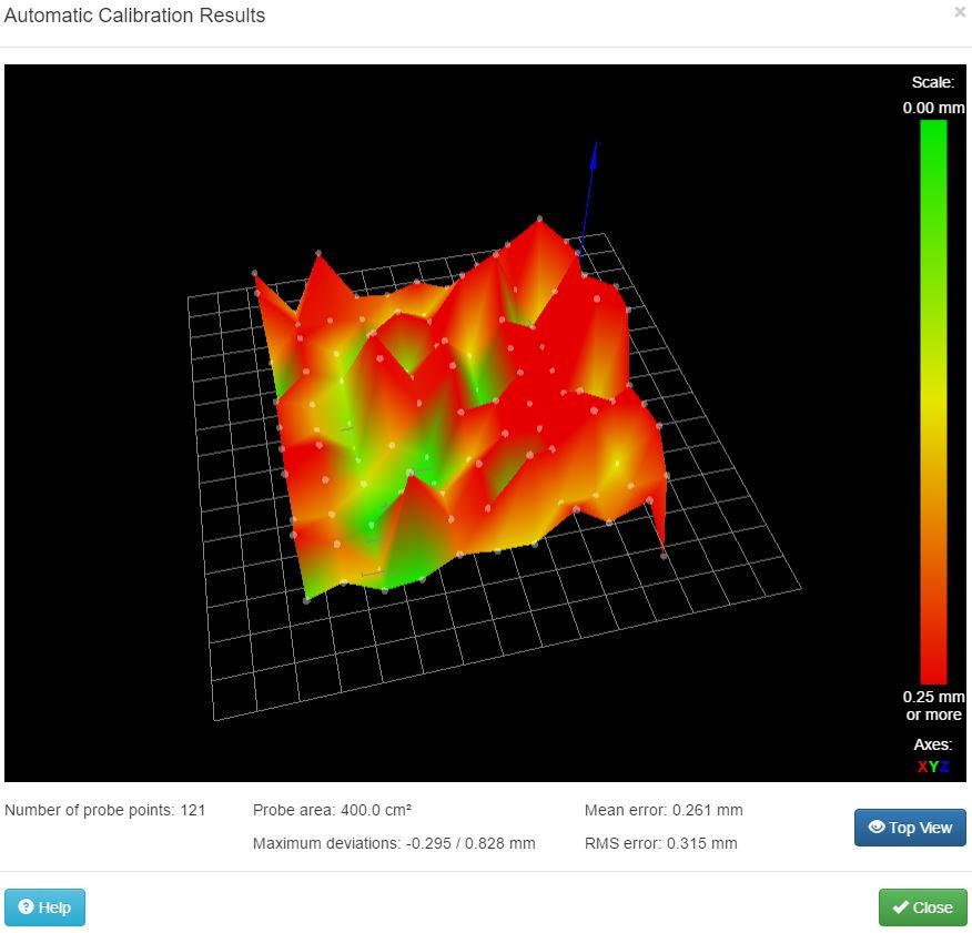
It does seem unlikely that your tooling plate is that uneven. So its either mechanical play or a sensor issue. I found the IR sensor to be quite good with printbite, no real issues with it. However perhaps try a contact sensor like the piezo system and see the difference.
This is what you want to see

I'm using 6mm tooling plate and printbite with a piezo hotend probe.
-
I'm fairly sure there is no mechanical play, it's a metal v-slot build. May play with probing speeds and sensor drop height to see if that has any impact (2mm at moment). Paint should be here soon - but there is no way that the probe heightmap correlates to the actual bed.
I'd love to try a piezo, but no piezo/control board and need to think how to mount in a titan extruder.
Is there a way to desensitise dc's IR Probe?
-
You can change the threshold value in G31 Px where x is the threshold from 0-1000 default 500.
Whether this will really smooth it out or just change the height at which it triggers by a few microns, I do not know.
-
The IR probe should always be used with a trigger threshold of 500, because it only outputs 4 different values - about 0, 465, 535 and 1000.
I think what you are seeing is variation in trigger height caused by reflections from behind the glass. A sheet of black or other dark paper between the glass and the bed plate will substantially reduce the variation. I have used all of the following:
- Painting the aluminium bed plate black with heat-resistance paint, cured in an oven
- Black paper (found in the art supplied department of a stationery shop) between the bed heater and the glass
- Printing an A4 sheet of paper all black (except the margins) and putting it under the glass
- Spraying the back of the transparent surface black and curing the paint in an oven (I haven't tried this with glass, but it worked well for me with PEI).
-
Well, I've ordered a board from Idris and piezo's from Ebay, so will have a play, once I figure out a suitable mount for a Titan extruder.
-
The IR probe should always be used with a trigger threshold of 500, because it only outputs 4 different values - about 0, 465, 535 and 1000.
I think what you are seeing is variation in trigger height caused by reflections from behind the glass. A sheet of black or other dark paper between the glass and the bed plate will substantially reduce the variation. I have used all of the following:
- Painting the aluminium bed plate black with heat-resistance paint, cured in an oven
- Black paper (found in the art supplied department of a stationery shop) between the bed heater and the glass
- Printing an A4 sheet of paper all black (except the margins) and putting it under the glass
- Spraying the back of the transparent surface black and curing the paint in an oven (I haven't tried this with glass, but it worked well for me with PEI).
Thanks David. I don't use glass. The readings are the same with both PrintBite and on new cast tooling plate (with the protective film still on). I have some paint coming, so will certainly try that, whilst having a look at this piezo method. I'm sure it must be something simple.
On my old RAMPS, i just probed the four corners and it worked (this is a cartesian printer), and there was a very minimal difference across the first printed layer for irregularities, and I suppose I could go back to 4 corners - but now, I have seen this weird height map, I want to fix it.
-
Thanks David. I don't use glass. The readings are the same with both PrintBite and on new cast tooling plate (with the protective film still on). I have some paint coming, so will certainly try that, whilst having a look at this piezo method. I'm sure it must be something simple.
Do you ever get a reading of about 1000 from the Z probe? That's possible if you are using a highly-reflective surface such as bare aluminium, especially with the older version 1.1 sensors. That reading indicates that the sensor is saturated, which would explain the height map you are getting. You might want to try resting a sheet of ordinary white paper on top of the tooling plate, and probing against that.
-
i have put M557 R85 S20
in my bed.g but when i try G29 it gives an errorError: No valid grid defined for G29 bed probing
please advise how to fix it. thanks!
-
Try sending that M557 command from the console and see what error message you get, and/or send M557 with no parameters to see what grid is in effect.


