Mesh calibration not working or what am I doing wrong?
-
If you mean to look at the program code, then unfortunately I am not good at programming.
-
no the image of the you see after running mesh bed compensation.
-
Hi,
Have you ever defined a probing grid that covers the entire bed?
If not would you do that, probe the bed and post the height map here?
Thanks.
Frederick
Printers: a E3D MS/TC setup and a RatRig Hybrid. Using Duet 3 hardware running 3.4.6
-
Made a calibration with the parameters: M557 X500:700 Y150:230 S20
RepRapFirmware height map file v2 generated at 2019-11-03 18:06, min error -0.633, max error -0.047, mean -0.346, deviation 0.137
xmin,xmax,ymin,ymax,radius,xspacing,yspacing,xnum,ynum
500.00,700.00,150.00,230.00,-1.00,20.00,20.00,11,5
 -0.329, -0.318, -0.282, -0.248, -0.238, -0.218, -0.195, -0.176, -0.133, -0.089, -0.047
 -0.377, -0.358, -0.342, -0.314, -0.324, -0.287, -0.280, -0.235, -0.199, -0.162, -0.118
 -0.484, -0.434, -0.434, -0.435, -0.375, -0.344, -0.337, -0.308, -0.259, -0.216, -0.163
 -0.541, -0.507, -0.491, -0.479, -0.467, -0.427, -0.433, -0.389, -0.338, -0.282, -0.226
 -0.633, -0.607, -0.580, -0.550, -0.533, -0.510, -0.484, -0.463, -0.407, -0.353, -0.298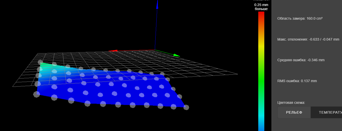
I still can’t understand what this can give us?
")
-
@fcwilt Bed Size X1380 Y1210
I only calibrate 500 x 500But the part fits in this size. It is inside a calibrated space.
Do you think if not the entire bed is calibrated this can cause an error? But how to do that? Maybe reduce the table and set offsets?
-
@Dep said in Mesh calibration not working or what am I doing wrong?:
@fcwilt Bed Size X1380 Y1210
I only calibrate 500 x 500But the part fits in this size. It is inside a calibrated space.
Do you think if not the entire bed is calibrated this can cause an error? But how to do that? Maybe reduce the table and set offsets?
One height map you posted was absolutely terrible.
I just want to get picture of the entire bed as a reference.
Not having the entire bed calibrated shouldn't cause an error unless you try to print outside that area.
But there is not much point in having a large bed if you cannot use it all.
Thanks.
Frederick
-
@fcwilt said in Mesh calibration not working or what am I doing wrong?:
One height map you posted was absolutely terrible.
I just want to get picture of the entire bed as a reference.
Not having the entire bed calibrated shouldn't cause an error unless you try to print outside that area.
But there is not much point in having a large bed if you cannot use it all.Now I can’t make a height map of the whole table, because glass 650 x 650 mm is fixed on the table
Yes, the bed is very crooked. But why doesn't compensation work? Does it really matter how rough the bed is?
-
@Dep said in Mesh calibration not working or what am I doing wrong?:
Does it really matter how rough the bed is?
with a bed as uneven as that it does.
the points in beetween probing are calculated and dont reflect what is actually there.
so if the bed is not uniformly uneven it will be off.
with it beeing off by an entire layer means this error can be significant. -
Yes, I agree, but the table is made of 4mm glass. It cannot be a “spasmodic” curve. I hope I wrote correctly
Those. the glass of course bends around the table, but these are smooth bends.
-
@Dep said in Mesh calibration not working or what am I doing wrong?:
Now I can’t make a height map of the whole table, because glass 650 x 650 mm is fixed on the table
Yes, the bed is very crooked. But why doesn't compensation work? Does it really matter how rough the bed is?
I see. Have you probed the glass area? Have you posted the height map here?
If you are limited to 121 points its going to be hard to get an accurate picture of that area
Probe a 220 by 220 area in the center of the glass and post the height map please.
Frederick
-
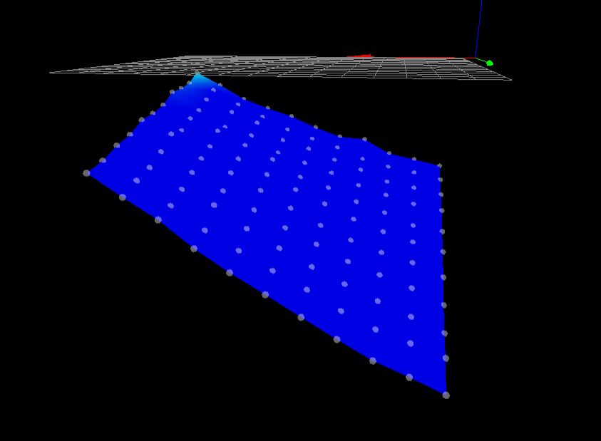
Ok, did it:
RepRapFirmware height map file v2 generated at 2019-11-03 19:31, min error -1.658, max error -0.124, mean -0.815, deviation 0.349
xmin,xmax,ymin,ymax,radius,xspacing,yspacing,xnum,ynum
600.00,800.00,300.00,500.00,-1.00,20.00,20.00,11,11
 -0.817, -0.773, -0.734, -0.627, -0.614, -0.546, -0.462, -0.402, -0.332, -0.225, -0.124
 -0.884, -0.839, -0.803, -0.752, -0.669, -0.608, -0.543, -0.447, -0.357, -0.249, -0.197
 -0.951, -0.911, -0.876, -0.794, -0.727, -0.650, -0.593, -0.466, -0.392, -0.303, -0.221
 -1.018, -0.982, -0.927, -0.866, -0.784, -0.719, -0.652, -0.532, -0.477, -0.361, -0.230
 -1.112, -1.084, -1.003, -0.936, -0.846, -0.780, -0.662, -0.569, -0.475, -0.394, -0.303
 -1.191, -1.137, -1.079, -1.004, -0.908, -0.821, -0.727, -0.628, -0.552, -0.449, -0.337
 -1.293, -1.210, -1.157, -1.087, -1.000, -0.896, -0.788, -0.681, -0.595, -0.441, -0.354
 -1.398, -1.303, -1.233, -1.160, -1.062, -0.968, -0.864, -0.753, -0.645, -0.521, -0.419
 -1.490, -1.404, -1.323, -1.231, -1.137, -1.033, -0.924, -0.789, -0.704, -0.581, -0.453
 -1.544, -1.474, -1.409, -1.314, -1.201, -1.101, -0.995, -0.886, -0.752, -0.614, -0.506
 -1.658, -1.574, -1.497, -1.390, -1.277, -1.162, -1.050, -0.925, -0.774, -0.658, -0.533
Offset down because the table is not heated now
-
please post the images as well
-
-
if you have a sloping x gantry the probe will be at an tilt angle. this will cause errors in the measurements as well.
-
I would suggest slowing down the probe speed of the BLTouch from 300 to 100. It's possible you're getting some bad probe points.
Are you able to manually level the bed with adjustment screws? It looks like there is a large amount of tilt.
The limited number of probe points with the older Duet board is going to make it difficult to get an accurate heightmap of such a large bed. The area between points is interpolated, but unless the surface is very flat to begin with, the risk is there for the interpolation to gloss over a defect.
Possible work around would be to modify your first layer parameters to compensate for the unevenness by using extra thick extrusion. Or perhaps using a raft.
-
I use M558 P9 H6 F300 T6000 R0.2 A5 B1 - where A5 - five times probe and usually it probe just 2 times, theni think bltouch work well. But i will test lower down speed of probing.
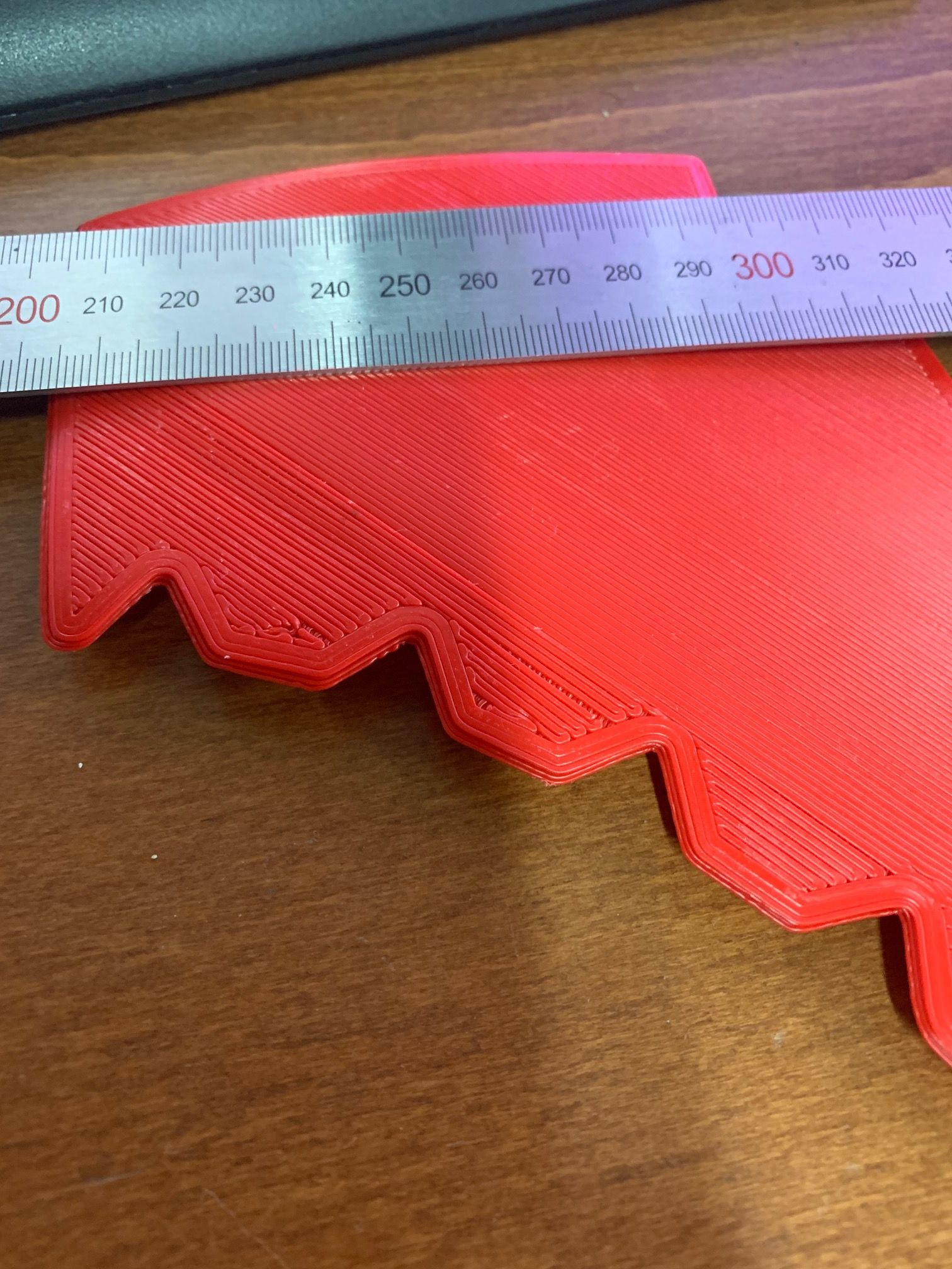
I agree that the table is very crooked and 50mm is a lot.
But look at the photo - there part of the model is at least have 3-4 points. Why is there no compensation?
-
@Dep said in Mesh calibration not working or what am I doing wrong?:
Why is there no compensation?
there is. your bed has a 1mm diffrence between both sides.
turn off compensation and print one without.
-
Hi,
Well at least the section seems pretty smooth even if badly tilted.
There are things you may be doing at the start of the print that are disabling mesh compensation.
Does the DWC interface show that mesh compensation is on? You can verify this during a print.
Frederick
Printers: a E3D MS/TC setup and a RatRig Hybrid. Using Duet 3 hardware running 3.4.6
-
@Dep Looking at the last two height maps you published, just one corner matches the plane which the firmware assumes to be the bed’s surface. Interestingly, the height map itself is quite consistent, i.e. relatively flat. It is just not in sync with the bed level. In order to cure this, you really should carefully level your bed and then calibrate Z=0 at its center, before you run another mesh grid calibration. As long as the resulting height map is not (at least partially) in sync with the assumed bed plane, it’s useless.
-
@fcwilt Yes, compensation is on. I checked the M122 command, and also it is visible since the bed moves up / down when printing.