• Tags
  • Documentation
  • Order
  • Register
  • Login
Duet3D Logo Duet3D
  • Tags
  • Documentation
  • Order
  • Register
  • Login

Mesh calibration not working or what am I doing wrong?

Scheduled Pinned Locked Moved Unsolved
Tuning and tweaking
11
93
4.9k
Loading More Posts
  • Oldest to Newest
  • Newest to Oldest
  • Most Votes
Reply
  • Reply as topic
Log in to reply
This topic has been deleted. Only users with topic management privileges can see it.
  • undefined
    Dep
    last edited by 4 Nov 2019, 08:09

    I agree with you that the smaller the distance between the points, the better the calibration.

    But the glass on the table cannot be bent strongly at a distance of 50mm.

    Look at the photo: why the calibration is not performed?
    2019-11-04_10-55-52.png

    undefined 1 Reply Last reply 4 Nov 2019, 08:47 Reply Quote 0
    • undefined
      dgrat
      last edited by dgrat 11 Apr 2019, 08:40 4 Nov 2019, 08:39

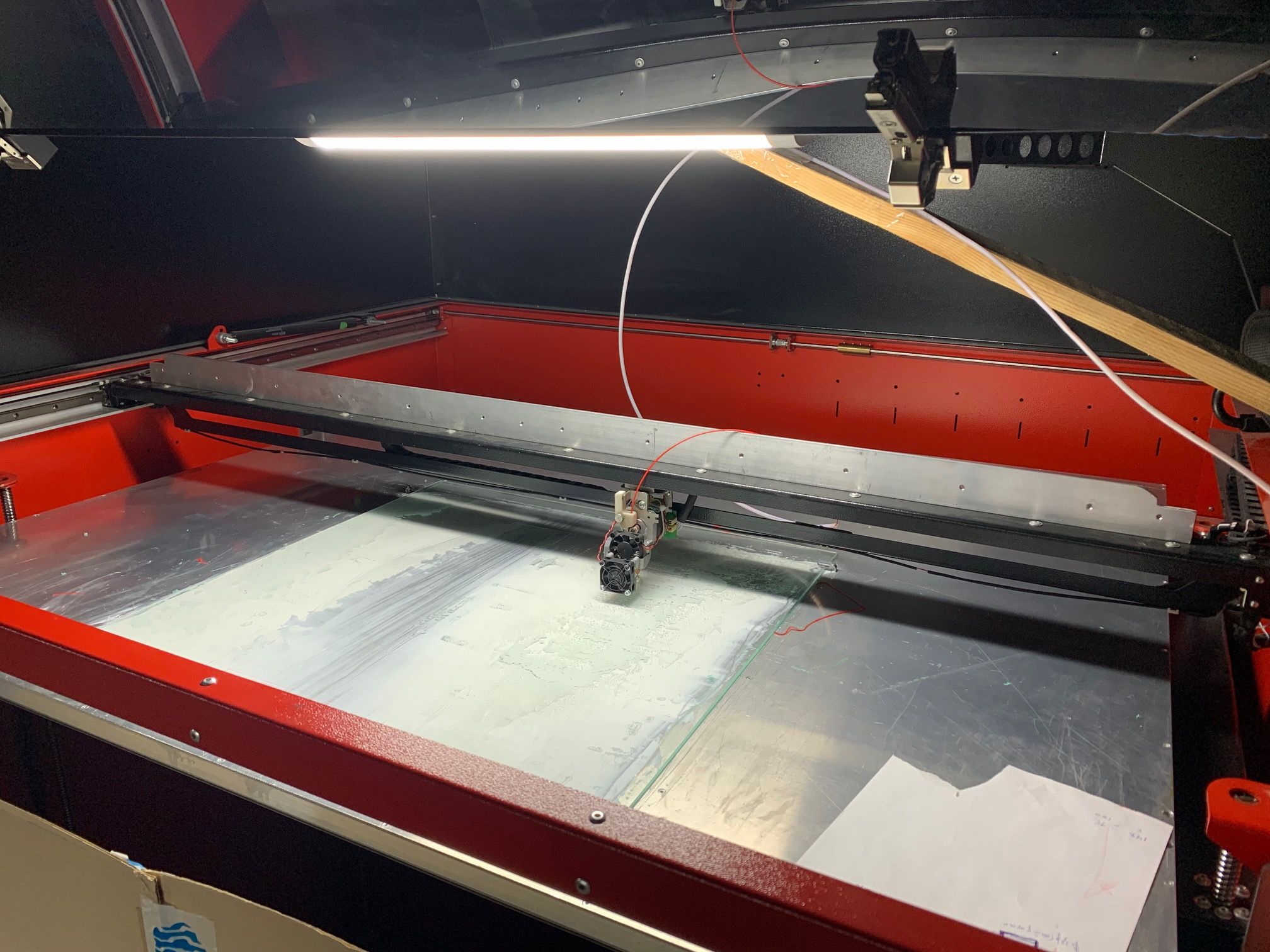
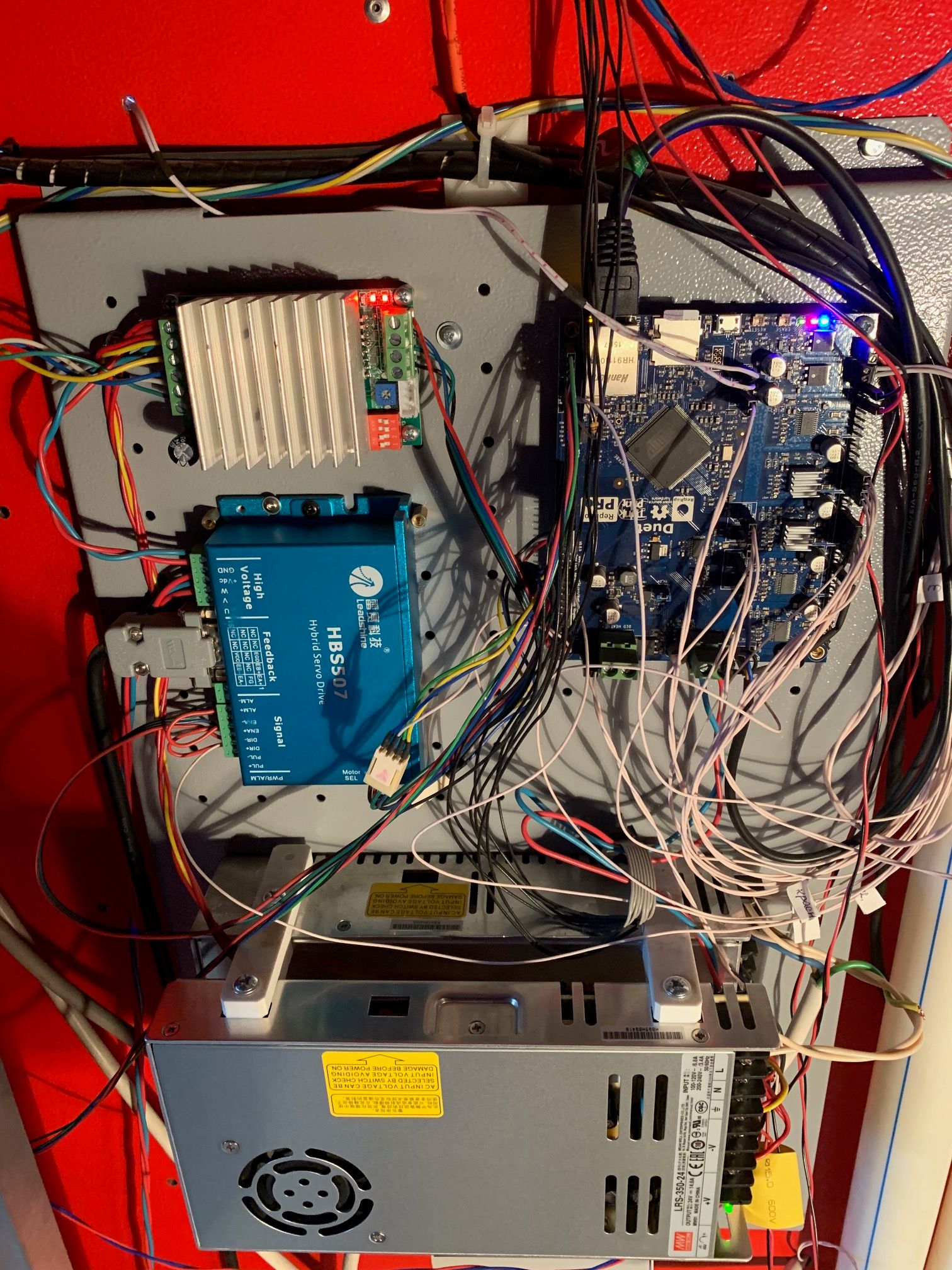
      Would you post some photos of your printer and the whole config.g file?

      1 Reply Last reply Reply Quote 0
      • undefined
        infiniteloop @Dep
        last edited by 4 Nov 2019, 08:43

        @Dep

        I warm up the bed and chamber , wait 1-2 hours and run mesh calibration two times and compare the resulting grid. If everything is ok, I'm trying to print.

        I understand that a printer of that size is difficult to handle. Fact is that the last two height maps you published do not look bad, they are just not in sync with the bed plane. In other words: the white grid in the height maps represents the result of your bed levelling, the coloured plane (mostly blue) demonstrates the measured distances at the probing points. These two „planes“ are way too far off from each other.

        Mesh grid compensation is not a substitute for proper bed levelling, ist is just an additional aid to smoothen the first layers. So, after you warm up bed and chamber, level the bed first, then, calibrate the mesh. If the resulting „planes“ do not match, something is wrong with your printer’s geometry.

        undefined 1 Reply Last reply 4 Nov 2019, 09:10 Reply Quote 0
        • undefined
          fcwilt @Dep
          last edited by 4 Nov 2019, 08:47

          @Dep said in Mesh calibration not working or what am I doing wrong?:

          I agree with you that the smaller the distance between the points, the better the calibration.

          But the glass on the table cannot be bent strongly at a distance of 50mm.

          Look at the photo: why the calibration is not performed?
          2019-11-04_10-55-52.png

          Hi,

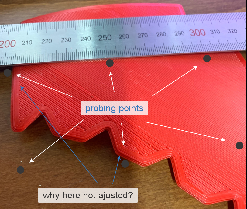
          Could you please print a simple 5 mm thick rectangle large enough that it includes that 6 probe points.

          The irregular nature of the object you are printing may be hiding another problem.

          Thanks.

          Frederick

          Printers: a small Utilmaker style, a small CoreXY and a E3D MS/TC setup. Various hotends. Using Duet 3 hardware running 3.4.6

          undefined 1 Reply Last reply 4 Nov 2019, 09:11 Reply Quote 0
          • undefined
            Dep @infiniteloop
            last edited by 4 Nov 2019, 09:10

            @infiniteloop The height maps are far apart because the table was not heated. Now I will make a new card on the heated table.

            However, even if they do not match. I want to understand - are there any restrictions on the size of the shift?

            undefined 1 Reply Last reply 4 Nov 2019, 19:08 Reply Quote 0
            • undefined
              Dep @fcwilt
              last edited by 4 Nov 2019, 09:11

              @fcwilt
              I will try to do. But it will take at least 4 hours 🙂

              undefined 1 Reply Last reply 4 Nov 2019, 12:20 Reply Quote 0
              • undefined
                Dep
                last edited by 4 Nov 2019, 10:36

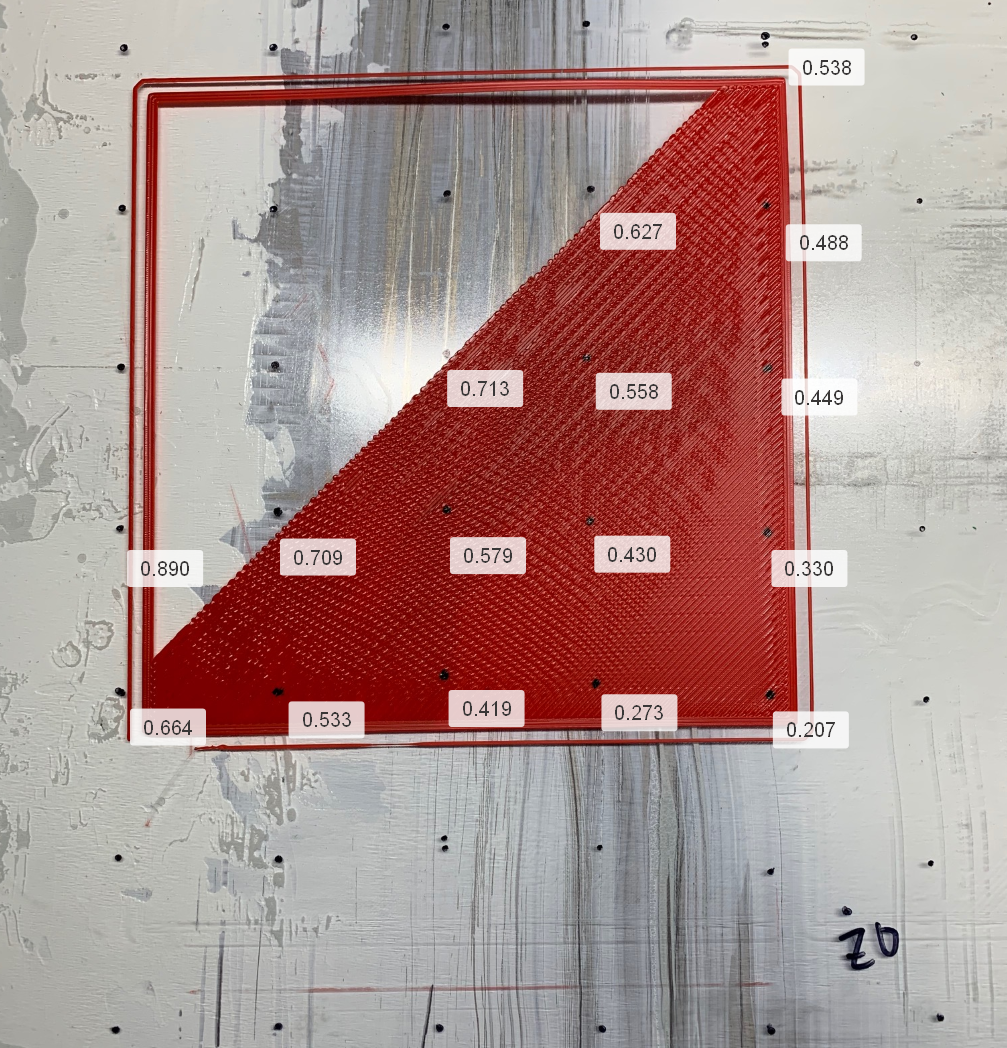
                I heated the table. Here is the result:

                RepRapFirmware height map file v2, min error -0.056, max error 1.271, mean 0.512, deviation 0.270
                xmin,xmax,ymin,ymax,radius,xspacing,yspacing,xnum,ynum
                450.00,950.00,120.00,620.00,-1.00,50.00,50.00,11,11
                0.210, 0.144, 0.077, -0.005, -0.047, -0.056, 0.005, 0.057, 0.157, 0.285, 0.423
                0.433, 0.364, 0.267, 0.133, 0.083, 0.066, 0.102, 0.179, 0.279, 0.408, 0.553
                0.664, 0.533, 0.419, 0.273, 0.207, 0.222, 0.234, 0.285, 0.372, 0.501, 0.646
                0.890, 0.709, 0.579, 0.430, 0.330, 0.267, 0.302, 0.367, 0.443, 0.563, 0.721
                1.078, 0.899, 0.713, 0.558, 0.449, 0.400, 0.405, 0.452, 0.515, 0.649, 0.782
                1.240, 1.019, 0.818, 0.627, 0.488, 0.458, 0.484, 0.534, 0.601, 0.694, 0.840
                1.271, 1.028, 0.831, 0.665, 0.538, 0.483, 0.478, 0.498, 0.598, 0.699, 0.806
                1.205, 0.980, 0.773, 0.632, 0.508, 0.471, 0.454, 0.509, 0.572, 0.698, 0.808
                1.080, 0.846, 0.679, 0.522, 0.405, 0.383, 0.417, 0.469, 0.556, 0.689, 0.792
                0.829, 0.671, 0.544, 0.382, 0.310, 0.332, 0.350, 0.437, 0.555, 0.698, 0.823
                0.687, 0.558, 0.428, 0.302, 0.217, 0.232, 0.278, 0.356, 0.468, 0.605, 0.752

                2019-11-04_13-36-23.png

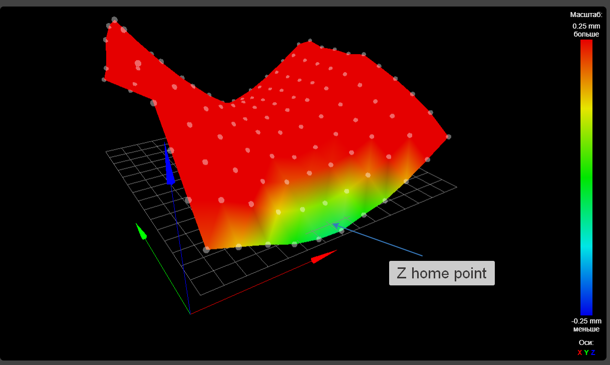
                And now I’ll try to print a 200 x 200 square ...

                1 Reply Last reply Reply Quote 0
                • undefined
                  dgrat
                  last edited by dgrat 11 Apr 2019, 11:14 4 Nov 2019, 11:09

                  M906 X1500 Y0 Z0 E1200 I100 ; Set motor currents (mA) and motor idle factor in per cent

                  looks weird. How does this even work? I also don't think, that test-printing makes sense currently.

                  M92 X100 Y160 Z1600 E157 ; Set steps per mm

                  I havent seen many builds like this. Can you post a photo. Why is Steps per mm all different?

                  undefined 1 Reply Last reply 4 Nov 2019, 12:02 Reply Quote 0
                  • undefined
                    Veti
                    last edited by 4 Nov 2019, 11:28

                    f5fca025-08ce-4d02-995a-15234abfd9cb-grafik.png

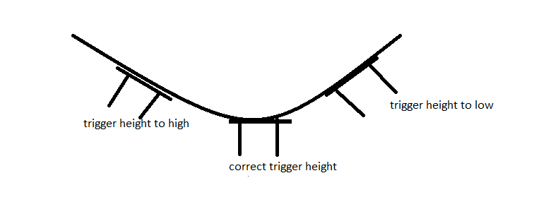
                    I made a crude drawing what happens with a sagging x axis to the trigger height.
                    the drawing is a bit over the top, but its just to show the problem.

                    because of the curve created by the sagging the trigger heights varies, which causes incorrect heights to be reported.

                    undefined 1 Reply Last reply 4 Nov 2019, 11:55 Reply Quote 0
                    • undefined
                      Dep @Veti
                      last edited by 4 Nov 2019, 11:55

                      @Veti Honestly, I did not understand your picture. Could be a little more detailed 🙂

                      undefined 1 Reply Last reply 4 Nov 2019, 12:11 Reply Quote 0
                      • undefined
                        Dep
                        last edited by 4 Nov 2019, 11:58

                        Pictures of the result:

                        2019-11-04_14-48-58.png
                        IMG_1188.jpg
                        IMG_1190.jpg
                        IMG_1189.jpg

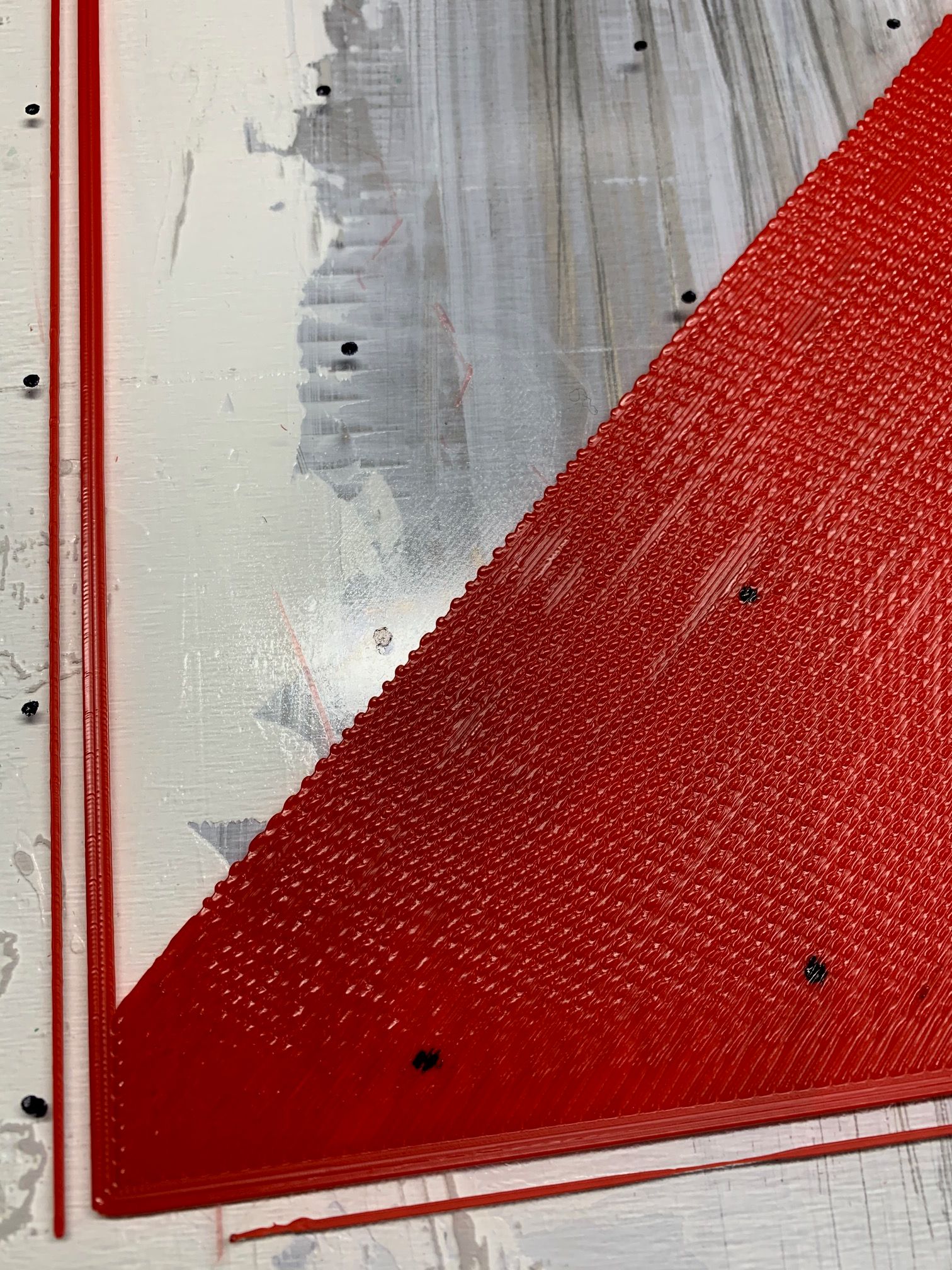
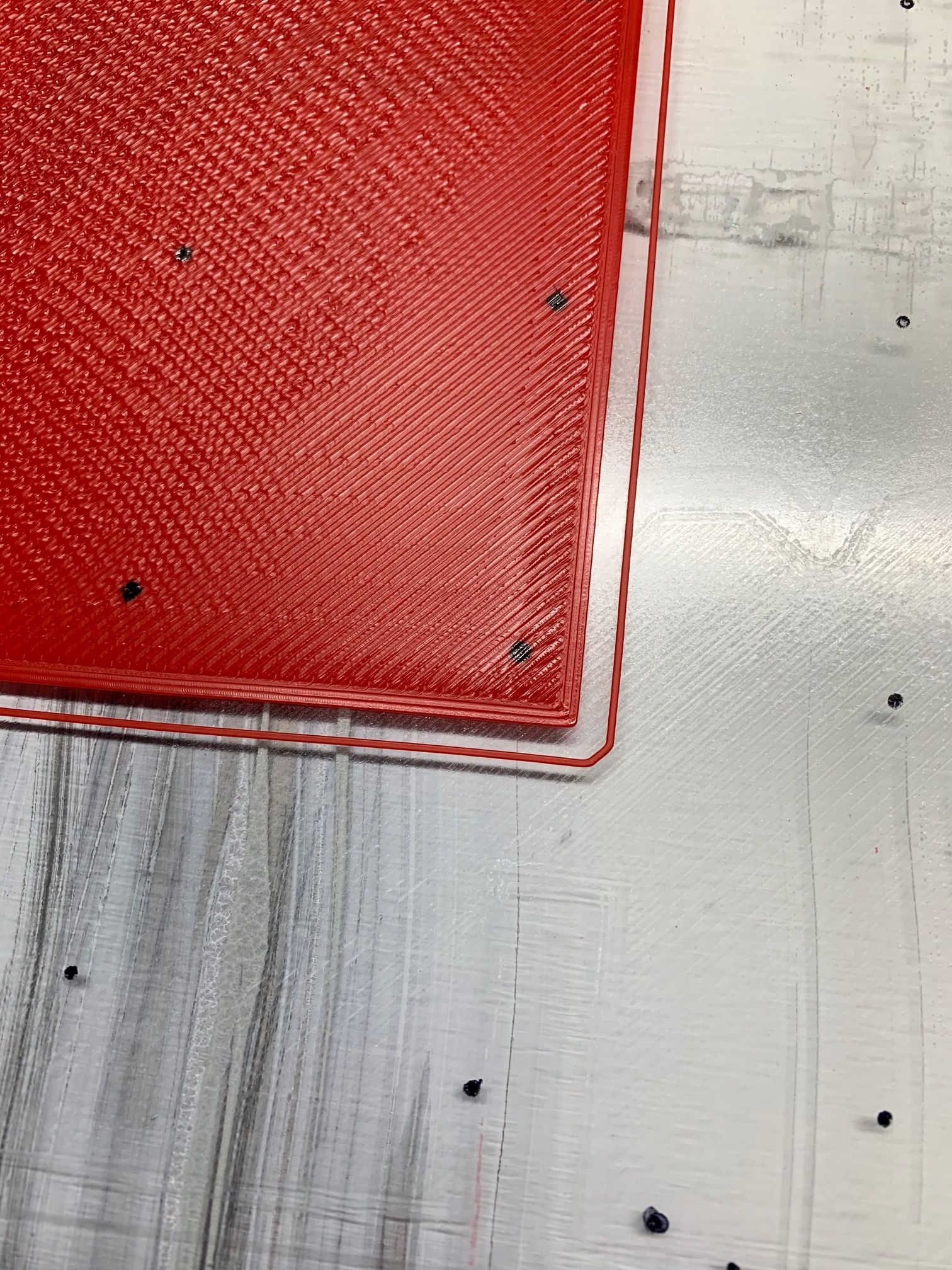
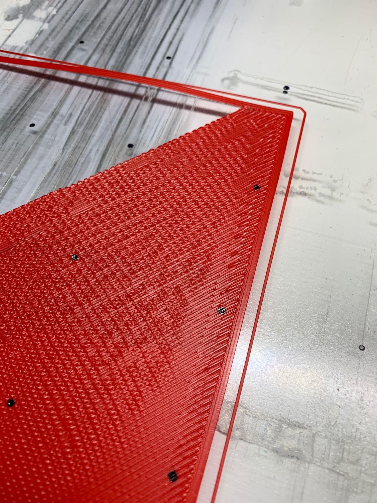
                        I should have made the bed a little lower, but it’s already clearly seen that the compensation is insufficient.

                        1 Reply Last reply Reply Quote 0
                        • undefined
                          Dep @dgrat
                          last edited by 4 Nov 2019, 12:02

                          @dgrat said in Mesh calibration not working or what am I doing wrong?:

                          M906 X1500 Y0 Z0 E1200 I100

                          This is because the Y and Z motors are connected to an external driver.

                          IMG_1179.jpg IMG_1180.jpg

                          1 Reply Last reply Reply Quote 0
                          • undefined
                            Veti @Dep
                            last edited by 4 Nov 2019, 12:11

                            @Dep
                            the images shows your over 1 meter long x axis.
                            it bends under its own weight

                            it shows your hotend assembly at 3 different positions.

                            1. at an angle in the at around 1/3 the length
                            2. not at an angle in the middle
                            3. at an angle at around 2/3 the length

                            because the entire hotend assembly is at an angle at position 1 and 3 the probe value will be off because in position 1 the nozzle is lower and in position 3 the nozzle is higher in comparison to the probes trigger point.

                            lets assume you have a trigger height of 5mm
                            i.e. at position 2 this is correct.
                            at position 1 your actual trigger height might be 6mm
                            at position your actual trigger height might be 4mm.

                            so your printer in the middle would be fine.
                            the further you move to the left your prints would get squashd
                            the further you move to the right your prints would be spaced or not stick to the bed.

                            p.s that bed surface looks like old scrap metal.

                            undefined 2 Replies Last reply 4 Nov 2019, 12:19 Reply Quote 0
                            • undefined
                              Dep @Veti
                              last edited by Dep 11 Apr 2019, 12:21 4 Nov 2019, 12:19

                              @Veti Now I understand what you mean.

                              I do not agree. The deflection of the extruder beam is almost zero. When it was mounted, we did a preload up. And checked on the line.

                              And even if there is a sag, then this is a hundredth of a millimeter.

                              The upper surface of the table is made of aluminum. To equalize and improve thermal conductivity, thermal grease was applied under the glass.

                              1 Reply Last reply Reply Quote 0
                              • undefined
                                fcwilt @Dep
                                last edited by 4 Nov 2019, 12:20

                                @Dep said in Mesh calibration not working or what am I doing wrong?:

                                @fcwilt
                                I will try to do. But it will take at least 4 hours 🙂

                                Thanks very much.

                                Frederick

                                Printers: a small Utilmaker style, a small CoreXY and a E3D MS/TC setup. Various hotends. Using Duet 3 hardware running 3.4.6

                                undefined 1 Reply Last reply 4 Nov 2019, 12:22 Reply Quote 0
                                • undefined
                                  Dep @fcwilt
                                  last edited by 4 Nov 2019, 12:22

                                  @fcwilt Already done. Look above 🙂

                                  undefined 1 Reply Last reply 4 Nov 2019, 12:38 Reply Quote 0
                                  • undefined
                                    fcwilt @Dep
                                    last edited by 4 Nov 2019, 12:38

                                    @Dep said in Mesh calibration not working or what am I doing wrong?:

                                    @fcwilt Already done. Look above 🙂

                                    Yes. I see. Thanks very much.

                                    I'm not sure what is going on. The numbers suggest that glass is very uneven.

                                    The printed object seems to show extrusion problems. Around the perimeter the lines look good, even if they didn't adhere, but the infill looks strange.

                                    The probing you did used a 50x50 (mm) grid correct?

                                    Have you tried probing a smaller area using a 10x10 or 20x20?

                                    I would be interested to see if such a small area exhibited the same strange numbers, when done on different areas on the glass, such as the middle versus the four corner.

                                    Frederick

                                    Printers: a small Utilmaker style, a small CoreXY and a E3D MS/TC setup. Various hotends. Using Duet 3 hardware running 3.4.6

                                    undefined 1 Reply Last reply 4 Nov 2019, 13:23 Reply Quote 0
                                    • undefined
                                      Dep @Veti
                                      last edited by 4 Nov 2019, 13:19

                                      @Veti I just measured the deflection of the X axis in the middle and it is less than 0.1mm

                                      You are right, this is a very interesting idea with a bltouch measurement angle! But unfortunately in this case is not applicable.

                                      1 Reply Last reply Reply Quote 0
                                      • undefined
                                        Dep @fcwilt
                                        last edited by 4 Nov 2019, 13:23

                                        @fcwilt Yes, I have already tried different options. On small objects more or less. But I'm interested in a big one.

                                        What is the use of mesh calibration if it requires a flat bed?

                                        Maybe you will try to lower the one corner of the bedon on your printer by 2-3mm and try to print something. Will calibration work?

                                        I think not.

                                        undefined 1 Reply Last reply 4 Nov 2019, 15:11 Reply Quote 0
                                        • undefined
                                          dgrat
                                          last edited by 4 Nov 2019, 15:04

                                          This post is deleted!
                                          1 Reply Last reply Reply Quote 0
                                          65 out of 93
                                          • First post
                                            65/93
                                            Last post
                                          Unless otherwise noted, all forum content is licensed under CC-BY-SA