Solved Solved - Again short-to-ground on replacement board - Duet 2 Wfi
-
Hello fellow printer(er?)s,
I've build a new Cartesian style printer and am trying to control it with a Duet 2 Wifi. All is well until I try and control the Z-motors. Trying to home with different acceleration and speed settings, none of them result in actual movement on the Z-axis. I do get a holding torque on them (motors). After several attempts to home with different settings the system eventually starts spamming the Error: short-to-ground by driver(s) 2. This error keeps being spammed until the idle time has run out (30sec in my case). Now this board is already a replacement board because the previous one had the exact same problem on the Z axis. For some reason the X and Y are fine.
Both Z-axis motors are being tested without any load on them, nothing is mechanically connected on them. All motors in my system are the same type, for all axis. Connecting the Z-motors on different drivers (X, Y) work without a problem, they start turning as expected.
I'm getting the suspicion the boards I'm receiving are experiencing a hardware failure of some sort on the driver(s). Help is greatly appreciated as I think my supplier isn't going to send yet another board.
Some specs:
Duet 2 Wifi FW v2.03
42HE3D-A1 motors: 1.7A 1.8deg (Dual Z-motor)
24VDC power supply (not a single under voltage alarm)
2mm pitch spindles on all axis (=1600 steps/mm)
Board mounted in a PETG 'box' on standoffs and a fan blowing from underneath
Config.g:; Configuration file for Duet WiFi (firmware version 2.03) ; executed by the firmware on start-up ; ; generated by RepRapFirmware Configuration Tool v2.0.5 on Tue Oct 29 2019 21:06:11 GMT+0100 (Midden-Europese standaardtijd) ; General preferences G90 ; send absolute coordinates... M83 ; ...but relative extruder moves M550 P"Getting-it-done" ; set printer name ; Network M552 S1 ; enable network M586 P0 S1 ; enable HTTP M586 P1 S0 ; disable FTP M586 P2 S0 ; disable Telnet ; Drives M569 P0 S1 ; physical drive 0 goes forwards M569 P1 S1 ; physical drive 1 goes forwards M569 P2 S1 ; physical drive 2 goes forwards M569 P3 S1 ; physical drive 3 goes forwards M569 P4 S1 ; physical drive 4 goes forwards M584 X0 Y1 Z2 E3:4 ; set drive mapping M350 X16 Y16 Z16 E16:16 I1 ; configure microstepping with interpolation M92 X1600.00 Y1600.00 Z1600.00 E420.00:420.00 ; set steps per mm M566 X100.00 Y100.00 Z100.00 E10.00:10.00 ; set maximum instantaneous speed changes (mm/min) M203 X250.00 Y250.00 Z250.00 E100.00:100.00 ; set maximum speeds (mm/min) M201 X100.00 Y100.00 Z100.00 E25.00:25.00 ; set accelerations (mm/s^2) M906 X500 Y750 Z1000 E500:500 I30 ; set motor currents (mA) and motor idle factor in per cent M84 S30 ; Set idle timeout ; Axis Limits M208 X0 Y0 Z0 S1 ; set axis minima M208 X300 Y300 Z300 S0 ; set axis maxima ; Endstops M574 X1 Y1 S0 ; set active low and disabled endstops ; Z-Probe M574 Z1 S2 ; set endstops controlled by probe M307 H3 A-1 C-1 D-1 ; disable heater on PWM channel for BLTouch M558 P9 H5 F120 T12000 ; set Z probe type to bltouch and the dive height + speeds G31 P500 X0 Y0 Z2.5 ; set Z probe trigger value, offset and trigger height M557 X15:250 Y15:250 S50 ; define mesh grid ; Heaters M307 H0 B0 S1.00 ; disable bang-bang mode for the bed heater and set PWM limit M305 P0 T100000 B4138 R4700 ; set thermistor + ADC parameters for heater 0 M143 H0 S120 ; set temperature limit for heater 0 to 120C M305 P1 T100000 B3988 R4700 ; set thermistor + ADC parameters for heater 1 M143 H1 S280 ; set temperature limit for heater 1 to 280C ; Fans M106 P0 C"Part" S0 I0 F500 H-1 ; set fan 0 name, value, PWM signal inversion and frequency. Thermostatic control is turned off M106 P1 C"Hotend" S0 I0 F500 H1 T50 ; set fan 1 name, value, PWM signal inversion and frequency. Thermostatic control is turned on ; Tools M563 P0 S"extruder 0" D0 H1 F0 ; define tool 0 G10 P0 X0 Y0 Z0 ; set tool 0 axis offsets G10 P0 R0 S0 ; set initial tool 0 active and standby temperatures to 0C M563 P1 S"extruder 1" D1 H1 F0 ; define tool 1 G10 P1 X0 Y0 Z0 ; set tool 1 axis offsets G10 P1 R0 S0 ; set initial tool 1 active and standby temperatures to 0C ; Custom settings are not defined -
@Tyoi said in Again short-to-ground on replacement board (Duet 2 Wifi):
M584 X0 Y1 Z2 E3:4
42HE3D-A1 motors: 1.7A 1.8deg (Dual Z-motor)
First. you should be running the motors at around 80% their rated current.
connecting 2 motors on the z stepper halfs their current.so at the moment you are running the motors at 500ma. that is not enough.
M584 X0 Y1 Z2:4 E3
try this and connect the second z to e1.
-
Hello Veti, thanks for your reply.
On https://duet3d.dozuki.com/Wiki/Choosing_and_connecting_stepper_motors it says motors should be run at 50-85% of their rated current. This page also lists the Z-motors are wired in series and not in parallel, so it actually does not half the amps but the voltage, hence the 24VDC PSU.
Also, the X and Y axis are working with a load, X is currently set at 500mA which moves the carriage as intended. Although I need to tune these currents (and speeds etc), it is enough to move the motor.
Connecting the Z motors to E0, E1, X and/or Y works, but seeing as I will be running the E0 and E1 for actual extruders this wont work as a permanent solution.
-
if you connect only one z motor this message does not appear?
just to rule out a bad motor. -
@Veti When I was busy troubleshooting I did switch both Z-motors for the X and Y axis (physically, on the frame and electrical) and the X and Y are now set as the Z-motors.
Still only X and Y work, and the Z not anymore, currently due to the error (?) no more holding torque either.
I have not yet tested if the error persists when I disconnect both Z-motors. Will do so this evening.
-
@Tyoi said in Again short-to-ground on replacement board (Duet 2 Wifi):
currently due to the error (?) no more holding torque either.
check your wiring and phases. just because they are the same motor does not mean that the phases are the same.
-
@Veti All motors have been tested, using multimeter and scope (especially after I received the replacement board to exclude such problems and not needlessly repeat a wiring error or similar).
Pairs are on the outer two pins on the connector: blk+grn, red+blu as also stated on the datasheet here and connected as mentioned in previously linked page: "Each stepper motor connector has four pins. You must connect the two wires for one phase of the stepper motor between the two pins at one end of the connector, and the wires for the other phase to the two pins at the other end." and using the Duet 2 wiring diagram here.
Will re-test this evening though, can't hurt to be sure-sure.
-
Pairs are on the outer two pins on the connector: .... You must connect the two wires for one phase of the stepper motor between the two pins at one end of the connector,.
I'm confused by what you are saying here. You say that one pair are using the outer two pins but the duet documentation says the two left pins.
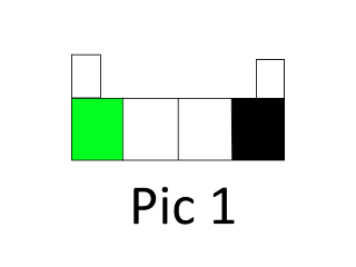
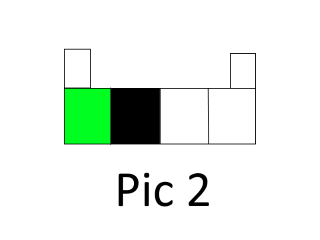
Lets take the black and green pairs as an example. Do you have them connected like pic 1 or pic 2 below?
Owns various duet boards and is the main wiki maintainer for the Teamgloomy LPC/STM32 port of RRF. Assume I'm running whatever the latest beta/stable build is
-
This post is deleted! -
-
That's no problem. Actual order doesn't matter as they work plugged in either way round.
-
Please check on the underside of your Duet that there are no solder bridges between pairs of pins of the Zb motor connector. Duets are tested with 2 jumpers in the Zb connector, so solder bridges there are not picked up during testing.
Also check that there is no chance of the back of the Duet shorting against anything below it; and if you have mounted the Duet on metal standoff pillars, that the pillar close to the Za motor connector isn't touching the adjacent Za connector solder joint on the underside of the Duet.
Duet WiFi hardware designer and firmware engineer
Please do not ask me for Duet support via PM or email, use the forum
http://www.escher3d.com, https://miscsolutions.wordpress.com -
@dc42 Hello dc42! I will check as soon as possible if any solder bridges exist as you mentioned.
I am very sure no shorting on the underside of the board is possible. The standoffs used are made of PETG (are part of the housing) and are 15mm high to provide ample ventilation. Also no metallic washers or such are used.
At the time of testing I actually only mounted the board with two screws, the top left one next to LED's indicating the heater status for the hotend(s) and voltages and on the bottom right at the expansion port. All screws used are smaller than the white circle on the PCB.
-
You get this error if you connected the motor phases the wrong way. Either by wiring, or by shorting. Use a Multimeter to find a phase. Then connect the phases according to the wiring diagram. If the motor does not spin, it should be enough to swap the cable of ONE of the phases either left or right pair (not entirely sure).
-
@dgrat said in Again short-to-ground on replacement board (Duet 2 Wifi):
You get this error if you connected the motor phases the wrong way. Either by wiring, or by shorting.
As @dgrat says. So please check that for each of the Z stepper motors, there is continuity between the 2 pins at once end of the 4-pin connector where it plugs into the Duet, and continuity between the 2 pins at the other end of the connector. Also check that there is no continuity between the 2 pins at one end and the 2 pins at the other end.
If the wires come directly out of the stepper motor with no connector, then the phase pairs are usually red-blue and green-black, but it's not impossible that a motor could have been manufactured incorrectly. If there is a 6-pin connector on the stepper motor itself, then the pinouts of those connectors vary between manufacturers, so you must always check which pairs of wires are the phases.
-
@dgrat @dc42 Thank you for the suggestions, will try/test first thing as I come back home.
The motors do have a connector on them, I will re-test the pairs on them to double check incorrect internal wiring.
Am I correct in assuming the error short-to-ground prevents any further movement from the drive but does not mean the driver is broken?
-
You can also test the motor:
- Phases should have continuity
- Shorting a phase must increase motor resistance when you want to spin it
If not, it's the motor. If yes, the wiring.
-
@Tyoi
Yes. At least in my case. Usually, it is a help that tells you that the wiring is faulty. -
@Tyoi said in Again short-to-ground on replacement board (Duet 2 Wifi):
Am I correct in assuming the error short-to-ground prevents any further movement from the drive but does not mean the driver is broken?
The short to ground message can mean any of:
- Motor phases incorrectly wired
- Shorted mosfet in the driver chip
- A genuine wiring short to ground
-
Gentlemen, -women,
Thank you for your help, I managed to resolve the situation. Indeed even though I had a batch of the same motors, with the same type no etc. there where internal wiring differences. For a few motors the pole pair wasn't on pin 1+2 or 3+4 but on 1+3 and 2+4. This was a learning moment for me seeing that in my experience using steppers I never had something like this happen to me. Perhaps these motors are a little bit too much 'china-y'.
What strikes me as weird though is that I have changed the motors on the board, testing the Z motors on the other steppers, which worked. So, not sure why.
Board is now working as intended, no more short-to-ground errors and sensorless homing seems to work a lot better on the X and Y axis now too.
Again thanks for the swift (correct) responses
")