Delta experts: feedback appreciated
-
-
@fcwilt said in Delta experts: feedback appreciated:
@bartolomeus said in Delta experts: feedback appreciated:
@fcwilt said in Delta experts: feedback appreciated:
@bartolomeus said in Delta experts: feedback appreciated:
I think I am almost done with th ebasic frame layout.
I just received an email about the Zesty Nimble V2. I did have a nimble before, but wasn't 100% satisfied.
Now I am in doubt about the extruder setup:- Fying extruder
- Nimble V2
- Or 4th axis extruder?
I have used Nimbles on all my printers and they have worked well for me.
What problems did you have?
It would be much simpler than a flying extruder.
Frederick
I never totally got rid of the wave pattern on the surfaces, even after I used the specified grease and also after they sent me a new worm gear.
Hmm...
I had problems with my deltas but that wasn't one of them. What was the supposed cause?
Frederick
In the beginning many people had wave patterns on the surface of their prints with a Nimble. Most of these patterns disappeared by replacing the supplied lubricant with some silicone grease. The Nimbles are now supplied as standard with the silicone grease I believe. But somehow I couldn't get rid of it.
-
@bartolomeus said in Delta experts: feedback appreciated:
In the beginning many people had wave patterns on the surface of their prints with a Nimble. Most of these patterns disappeared by replacing the supplied lubricant with some silicone grease. The Nimbles are now supplied as standard with the silicone grease I believe. But somehow I couldn't get rid of it.
Thanks for that info.
I guess I got lucky.
Frederick
-
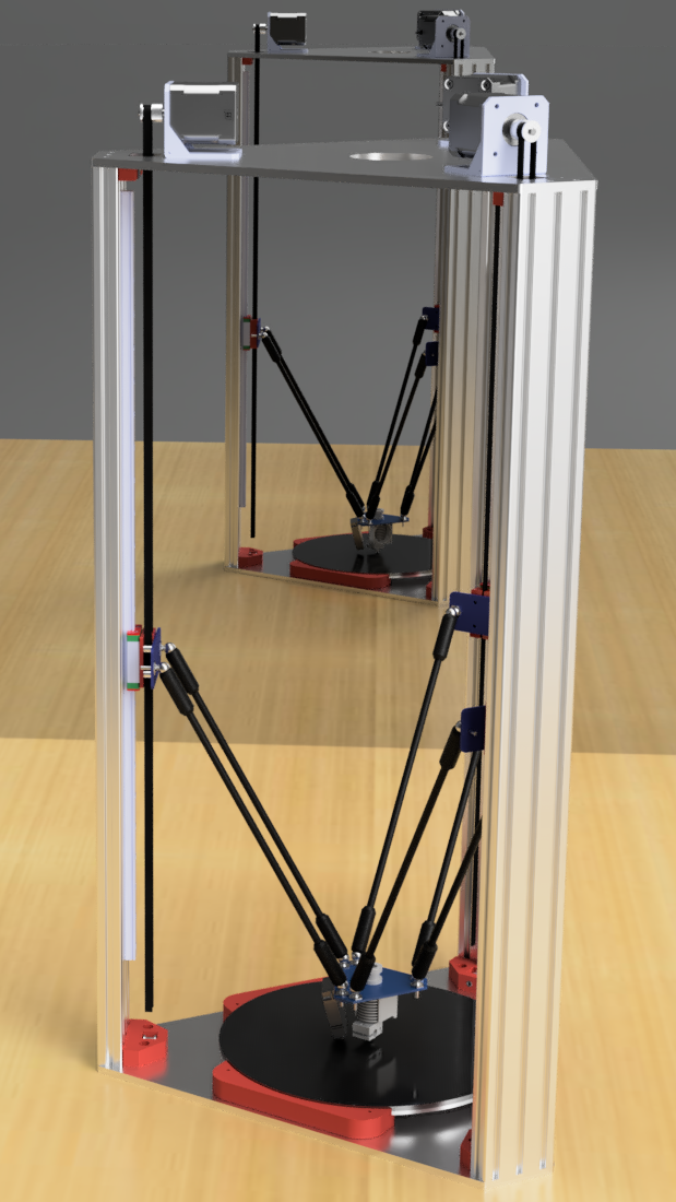
Whilst waiting for parts to arrive, I modified the design to a standard 3 tower delta. As a result the footprint is alot smaller.
-
I wonder if you will be able to get the vertical extrusions square to the base and top.
Screws into the ends of the extrusions won't have much leverage.
Looking forward to your progress.
Thanks.
Frederick
-
@fcwilt said in Delta experts: feedback appreciated:
I wonder if you will be able to get the vertical extrusions square to the base and top.
Screws into the ends of the extrusions won't have much leverage.
Looking forward to your progress.
Thanks.
Frederick
Same here. I am relying on the supplier of the extrusions that they are precisely cut and the same length.
Otoh, the 3 tower frame is only 5 parts (2 plates and 3 towers). My (upgraded) Anycubic Delta frame was made of 18 parts (6 corners, 3 towers, 9 horizontals) and it printed pretty good. I am hoping the lower part count and precisely machined parts will pay off.
-
@bartolomeus said in Delta experts: feedback appreciated:
@fcwilt said in Delta experts: feedback appreciated:
I wonder if you will be able to get the vertical extrusions square to the base and top.
Screws into the ends of the extrusions won't have much leverage.
Looking forward to your progress.
Thanks.
Frederick
Same here. I am relying on the supplier of the extrusions that they are precisely cut and the same length.
Otoh, the 3 tower frame is only 5 parts (2 plates and 3 towers). My (upgraded) Anycubic Delta frame was made of 18 parts (6 corners, 3 towers, 9 horizontals) and it printed pretty good. I am hoping the lower part count and precisely machined parts will pay off.
These are the reasons why I went with 4060 on mine, because it has a wider base and instead of the screws being all on one dimension, they're on two.
I also got mine milled square by a machine shop. It's incredibly accurate when done right.
-
@blt3dp said in Delta experts: feedback appreciated:
@bartolomeus said in Delta experts: feedback appreciated:
@fcwilt said in Delta experts: feedback appreciated:
I wonder if you will be able to get the vertical extrusions square to the base and top.
Screws into the ends of the extrusions won't have much leverage.
Looking forward to your progress.
Thanks.
Frederick
Same here. I am relying on the supplier of the extrusions that they are precisely cut and the same length.
Otoh, the 3 tower frame is only 5 parts (2 plates and 3 towers). My (upgraded) Anycubic Delta frame was made of 18 parts (6 corners, 3 towers, 9 horizontals) and it printed pretty good. I am hoping the lower part count and precisely machined parts will pay off.
These are the reasons why I went with 4060 on mine, because it has a wider base and instead of the screws being all on one dimension, they're on two.
I also got mine milled square by a machine shop. It's incredibly accurate when done right.
I did start out with a design based on 4060, but figured it would be overkill for a 240mm bed. I have already started on a 320-330mm bed version which will use 4060, however I am not sure if I will continue with the design or if I will build it.
-
@fcwilt said in Delta experts: feedback appreciated:
I wonder if you will be able to get the vertical extrusions square to the base and top.
Screws into the ends of the extrusions won't have much leverage.What exactly do you mean with "won't have much levarage?"
Im am not an engineer, but my gut tells me that the direct metal to metal construction without corners will be much stiffer than anything that does use corners. The cuts of the extrusions will indeed have to be precise, but getting anything using corners precise and straight is also a PITA... Maybe the construction will gain stiffness if the verticals are rotated 90 degrees. -
@DeltaCon said in Delta experts: feedback appreciated:
What exactly do you mean with "won't have much levarage?"
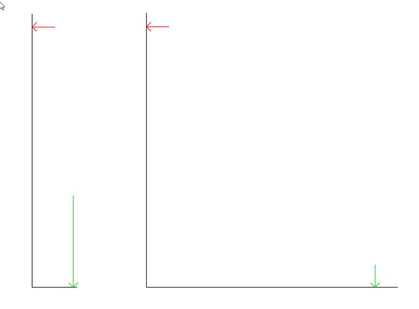
The extrusions are going to be tall in relation to their cross section.
Consider the diagram below. For a given force applied at the red arrow, to counteract that the required force applied at the green arrow on the right is going to be less than the required force applied at the green arrow on the left, because the lever arm is longer proving more leverage.
Frederick
-
Thanks, that much physics I do understand
")
In the left figure however, there is only one surface getting that force applied and possibly giving room for error. In the right fugure, if you use corner brackets, or those ugly cube-shaped things(that are often unsquare by default) you aply the force to more contact surfaces so giving more room for error. In my opinion it is not about the length of the arms, but about the stiffness of the joint. Less is more in this case. -
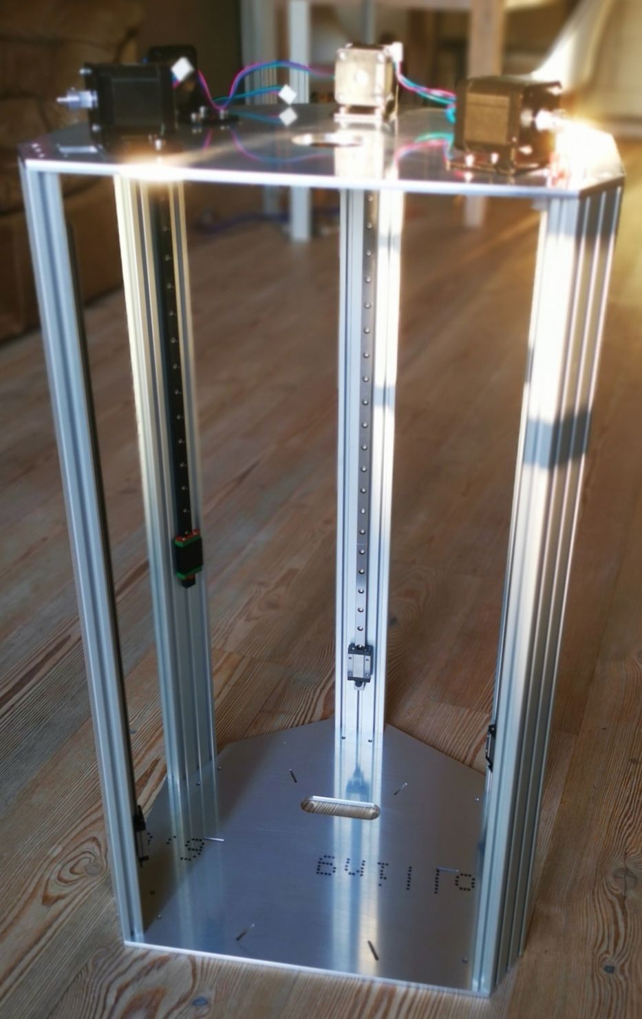
Fun has started:
-
This delta looks awesome!
Is there any chance you'll be making the design available for others to create their own?
-
@Munce31 said in Delta experts: feedback appreciated:
This delta looks awesome!
Is there any chance you'll be making the design available for others to create their own?
Thanks!
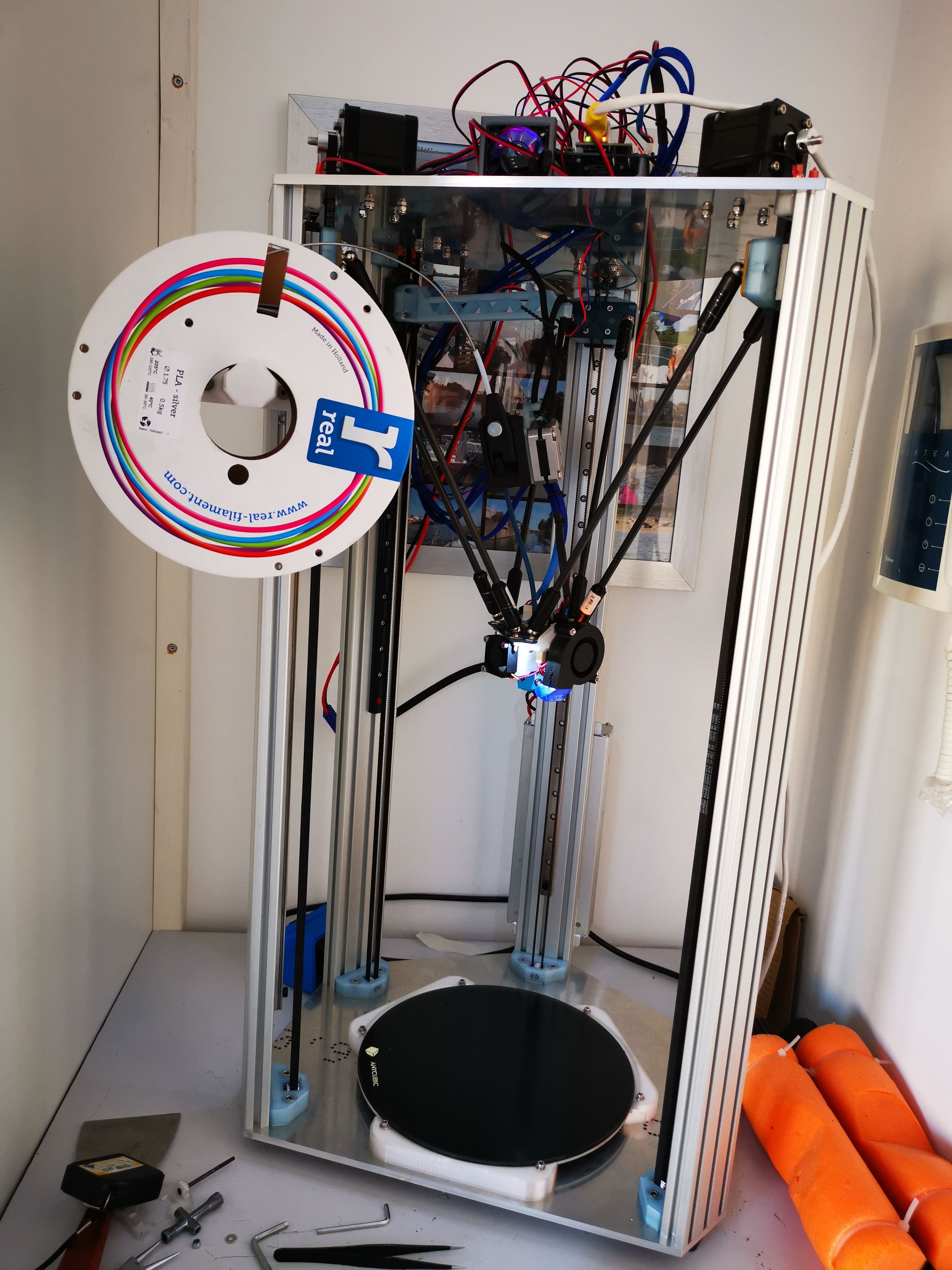
I am quite happy myself. Just finished building and started using the printer. With a bowden for now, waiting for the last parts to arrive to install the 4th axis. Calibrated to 0.01 deviation, which seems ok to me. Tbh I haven't even aligned the rails yet. Also the idler mounts need a slight adjustment. I might be able to move the idler mounts up and still clear the effector. This way it will be easier to tighten the belts, and also shorten the belts.Edit: oh, and yes I might make the designs publicly available. Will take some time though untill I have everything sorted out.
-
I am about to receive the last parts to setup the 4th axis.
Now I have a question about firmware configuration: I want the extruder output to keep the same distance from the hotend as when all axis are homed (the endstop of the 4th tower will be mounted lower than xyz endstops). How should I calculate the 4th axis 'rod length?M665 L288:288:288:?? R140 H340 B117.5
-
@bartolomeus: I never thought a 4th axis would be interesting because I thought, probably a false assumption, that the shorter bowden would be stressed during moves. If there is a possibility to keep the correct distance from hotend to extruder given the position of the extruder, that makes a significant difference! So I am curious about an answer to your question
Also: Do you have some newer pictures of the machine in use?
-
@DeltaCon said in Delta experts: feedback appreciated:
@bartolomeus: I never thought a 4th axis would be interesting because I thought, probably a false assumption, that the shorter bowden would be stressed during moves. If there is a possibility to keep the correct distance from hotend to extruder given the position of the extruder, that makes a significant difference! So I am curious about an answer to your question
Also: Do you have some newer pictures of the machine in use?
I installed everything last night and configured the 4th axis in the software. Everything is working nicely (printed a large vase to test the setup). Next step is to find how short I can go on the bowden. I doesn't look like the bowden gets stressed much, even on my temporary and fairly rigid extruder mount. I plan on using a short rubber band between the extruder and the carrier so that any tension on the bowden is further reduced. Btw, software maintains a set distance between extruder and hotend, minimising any stress on the bowden.
I don't have any news pics, it looks quite messy right now. I have to clean up some wiring first.
-
@bartolomeus said in Delta experts: feedback appreciated:
I installed everything last night and configured the 4th axis in the software. Everything is working nicely (printed a large vase to test the setup). Next step is to find how short I can go on the bowden. I doesn't look like the bowden gets stressed much, even on my temporary and fairly rigid extruder mount.
Some people mount the extruder on gimbals, so that the output direction of the Bowden tube can swivel to accommodate the XY position of the effector.
-
@dc42 said in Delta experts: feedback appreciated:
@bartolomeus said in Delta experts: feedback appreciated:
I installed everything last night and configured the 4th axis in the software. Everything is working nicely (printed a large vase to test the setup). Next step is to find how short I can go on the bowden. I doesn't look like the bowden gets stressed much, even on my temporary and fairly rigid extruder mount.
Some pole mount the extruder on gimbals, so that the output direction of the Bowden tube can swivel to accommodate the XY position of the effector.
I thought about a gimbal, but an elastic band seems like a simpler solution.
@dc42 The rail I am using for the 4th axis is too short, 400mm(build height is 340mm). It was a spare I had lying around. Is there a way to limit the movement of the 4th axis?
-
With an elastic band or gimbal, it is the effector that is moving the extruder. I want to eliminate any interaction between the two, so I think I am going to hard-mount the extruder to the 4th axis.
@DeltaCon attached a pic of the current state of the printer