Mesh calibration not working or what am I doing wrong?
-
@tarantul said in Mesh calibration not working or what am I doing wrong?:
How many optimal points are needed?
if there are problems with the first layer. increase the number of points.
-
@Dep said in Mesh calibration not working or what am I doing wrong?:
The height maps are far apart because the table was not heated. Now I will make a new card on the heated table.
In the meantime, you have posted a height map of your heated bed. It is quite similar to the first map in your thread, and it is equally frightening. Your bed heater must be a real weapon of mass-distortion

The bed is driven by four lead screws - do you allow the bed to expand horizontally, or are the suspensions fixed?
Are there any restrictions on the size of the shift?
I don’t know how the mesh grid compensation is implemented, but it is meant to level the print over the first few layers. See M376 for reference. In my experience, it helps a lot with the last some hundredth of a mm, but it is difficult to compensate differences in the range of several layer heights.
-
I am gonna throw a few things in here because I had a long journey getting the compensation to work on my machine. In my case it was twist in the X axis causing the problem, but it took me a long time to discover because I was just randomly changing settings and hoping for improvement rather than using a systematic approach.
There are several possibilities where the bed compensation could have problems. In order to troubleshoot systematically you'll need to build a list of potential error sources, and then troubleshoot by eliminating variables and testing what remains until you narrow down the root cause of the issue.
Every time I made a change, I would take another height map reading and save it into an excel spreadsheet. This allowed me use the charting tools and math functions to easily visualize and compare different readings to see what the similarities and differences were, and to see if I was making improvement over time.
There are many potential sources of errors in the bed map process. You'll have to come up with your own list, but here is what I ended up checking on mine:
-
Probe itself. Could be poor repeatability on the component. I replaced my bltouch with a simple microswitch just for testing purposes. Didn't change anything in the height maps, which eliminated the probe as a source of error.
-
Probe mounting location. This is a big one, particularly if the probe is in front of or behind the nozzle, any twist in the X axis could lead to incorrect readings due to the cosine error of the measurement. This will normally present as a 'tilted' height map, where one side is significantly higher than the other and it's fairly even over the distance. If there is a lot of downward deflection in X you would normally see a humped height map where the center is higher than left and right edges. This ended up being the problem in my case as my X axis was tilted. My probe was mounted far enough from the nozzle in X that a slight tilt was enough to introduce more than 0.4mm deviation into the readings.
-
Probe offsets. Large offsets can cause issues for mechanical reasons as above. Just validate the numbers otherwise. I think this is correct for you so unlikely to be an error source.
-
Interference in wiring between probe and duet. I replaced the existing wiring harness with a shielded wire just for testing which was ran far away from motor wires etc. This didn't change readings at all so it eliminated cable interference as a significant error source.
-
Temperature variation. Make sure at least the bed is stabilized to print temp before probing as it will certainly affect level. If you have a plastic probe mount it could possibly be softening slightly with temperature and changing readings as well (not terribly likely but possible). In my case this did make a big difference in readings between temperatures. My process is now to re-run the height map when I change materials with a significant difference in bed temp (from PLA to Polycarbonate for example)
-
Height map generation within firmware. You can check that this is OK by manual bed map generation. You can make one by attaching a dial indicator or similar. Fasten it to the extruder so it rides the carriage around. Record readings at various points to manually generate a height map csv file for the firmware. Compare this to the automatically generated maps. Load it up, then check to see if the compensation is better or worse. If the compensation is correct with a manual map, then something in the automatic map generation step is the source of the problem. If the compensation does not change or gets worse, then it's more likely to be with the compensation math / implementation itself (or the manual readings were taken incorrectly). In my case the manually generated map did not match the automatically generated map, which indicated problems with the automatic map process.
-
Compensation within firmware. You can make a fake height map with some easy to visualize error, such as a straight left-right variation of 5mm or so. Then just move across the bed with compensation enabled to ensure the system moves the expected amount. A dial indicator as above is a very helpful tool for this. In this case you would leave the dial stationary on any point in the bed, just to measure Z axis motion only. For my machine the compensation with the manually generated map worked perfectly, which indicated that the problem was NOT in the application of compensation but rather in the height map generation process or probe.
Sorry for the novel, hope this helps

-
-
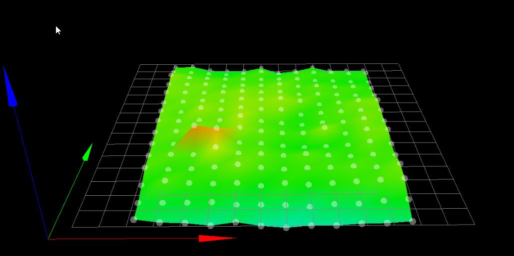
Hi,
There was some question about mesh compensation working on your printer.
The attached is my height map when probing 180 points (12x15) on a 20x20 mm grid using a BLTouch v3.0.
You can see a high spot on the left. I use a textured build surface on glass on aluminum. The build surface has an adhesive back. I think the high spot is because I didn't get it adhered evenly.
In any case when mesh compensation is enable I can see the Z axis stepper turning small amounts when printing in the area of the high spot.
The prints come out fine despite that high spot being appx 0.17 mm higher than most of the other points.
I am using a Duet WiFi with 2.04 firmware.
Frederick
-
@fcwilt
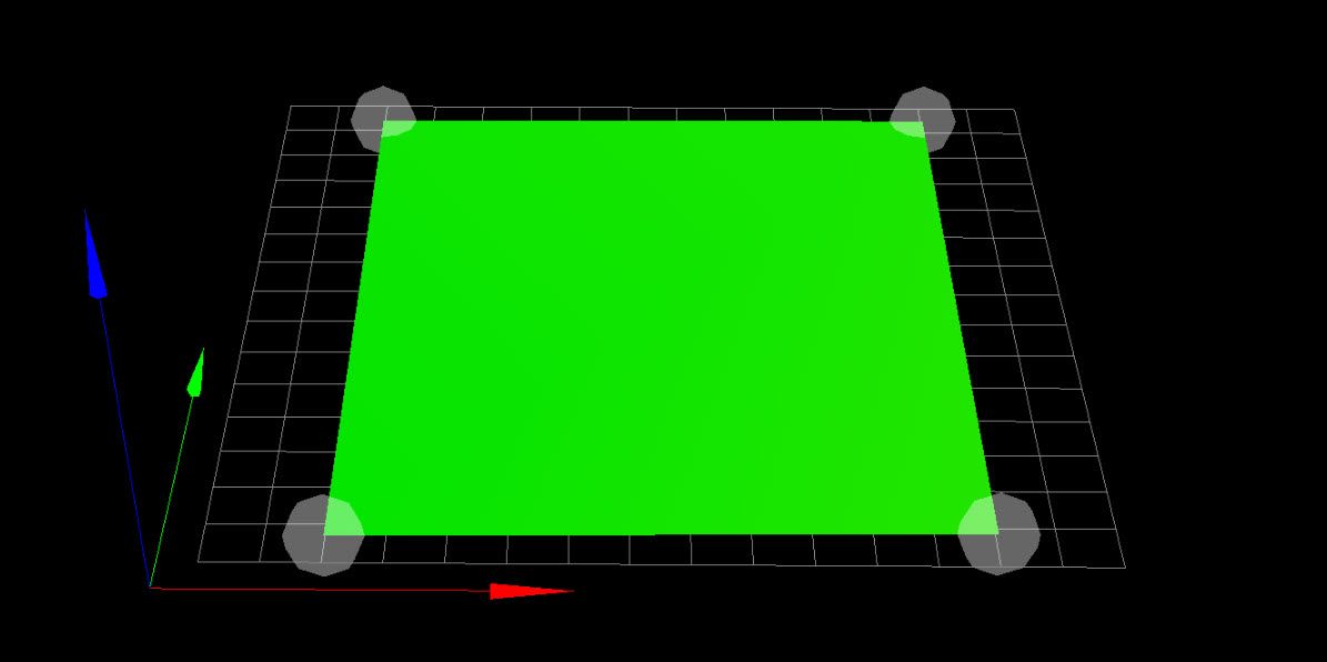
that bed would be a good way to illustrate the problem of to few probing points.can you just for demonstration reduce the number of points by lets say 4 and post the picture?
-
Hi,
I much prefer this height map done with just four points near the corners of the bed.
It makes my printer building skills look so much better.
Sadly it doesn't print as well with just these four points of compensation.
But the bed looks great doesn't it!!!!
")
-
I think now the main problem is skipping steps in Z
On the Z axis I have a Leadshine hybrid servo drive HBS507
And all that tested before that was with the setup of the M569 P7
After the last print, I noticed Hiccups 64
Next, I made the M569 P7 T2.5: 2.5: 5 - no result
Then M569 P7 T5: 5: 6 and Hiccups 20, and got better print
Then M569 P7 T20 and even better print and Hiccups 4
True, I constantly executed the M122 command during the printing process - it seems that it resets HiccupsWhere to go next? What should be the timings for my motor?
-
@nhof thank you very much! Take note of your recommendations!
-
@Dep said in Mesh calibration not working or what am I doing wrong?:
I think now the main problem is skipping steps in Z
On the Z axis I have a Leadshine hybrid servo drive HBS507
And all that tested before that was with the setup of the M569 P7
After the last print, I noticed Hiccups 64
Next, I made the M569 P7 T2.5: 2.5: 5 - no result
Then M569 P7 T5: 5: 6 and Hiccups 20, and got better print
Then M569 P7 T20 and even better print and Hiccups 4
True, I constantly executed the M122 command during the printing process - it seems that it resets HiccupsWhere to go next? What should be the timings for my motor?
May want to start a new thread with the Leadshine servo question to get some more views.
-
@Phaedrux yes thanks!
-
I started new tread about Leadshine hybrid servo drive tuning
https://forum.duet3d.com/topic/12762/leadshine-hybrid-servo-drive-tuning