Markforged Kinematics Troubleshooting
-
@fcwilt Actually just tried that a few minutes ago and it worked! now my issue is that I need the carriage to home in what is now the +x direction (with it having the correct motion). I would like to invert the X motor so that it goes in the correct direction but I'm not sure if I can do that now.
Wondering if I need to set a new matrices of motion with the M669 command to make that work
-
The direction it homes in is based on where you configure the location of the endstop "switch".
If it is configured at the low end, homing is in the direction of axis min. Likewise if it is configured at the high end, homing is in the direction of axis max.
Of course you have to actually have the endstop "switch" where you say it is, unless you are using stall motor detection for homing. I've never tried that, I like actual switches.
Frederick
-
@fcwilt I have it configured to home on the low end; I guess I just want to switch the location of the X axis min from the right to left side of the machine while keeping movement the same. My only other option is to flip my gantry 180 degrees.
I agree, I think physical endstop switches are better than stall detection.
-
If you issue a positive, relative movement on the X axis what direction does it move?
Frederick
-
@fcwilt If I am facing the machine, the X motor is on the back left of the machine and the Y is the back right.
With the motor directions set correctly (Y movement does not alter X position) a positive movement in the X axis moves the carriage to the left.
The problem being I would like movement to the left to be negative movement such that the front left corner of the machine is the 0,0 position.
I think it may be possible to do this by reversing the direction of the X motor and then using M669 with X being just the X motor and Y being a combination of the Y motor with a reversed X motor. Not sure if you can reverse directions within that command, however.
-
So positive movements of Y are to the back?
With a CoreXY machine there was a process to get everything moving correctly with the min/max ends where they belonged.
I would think there is a similar process for a MarkForged.
On the MarkForged machine I am designing/building I have reached the stages there the Y and Z axes hardware is done and working.
Tomorrow I start printing the parts for the X axis.
I may run into the same direction problem.
Frederick
-
@fcwilt Yes, positive Y moves the gantry towards the back of the machine.
Do you happen to know if its possible to set the kinematic gcode command M669 to something like this:
M669 X0 Y-0:1 Z2
With 0 being the X driver and 1 being the Y driver. In theory, with having the motor direction reversed on the X motor, using a negative when defining the motor movement for Y should fix my issues, i.e. let the X carriage home min to the left, have Y home min to the front.
-
Hi,
Well that is what the command is for though you would think the defaults ought to work.
M669 by itself will report the defaults.
Frederick
-
@fcwilt Got it fixed and moving correctly! I had to reverse the motor direction for the X motor, and also changed the value for the X motor to a positive in the Y axis of the kinematics matrices.
Current matrices:
M669 X1:0:0:0:0 Y 1:1:0:0:0 Z0:0:1:0:0 U0:0:0:1:0 W0:0:0:0:1
old matrices (default markForged kinematics, K11):
M669 X1:0:0:0:0 Y -1:1:0:0:0 Z0:0:1:0:0 U0:0:0:1:0 W0:0:0:0:1(note: U axis is for a tool locking mechanism, W axis is for a nozzle wiper)
@dc42 Thought I'd tag you in this, since I haven't seen much info on the forums regarding getting Markforged kinematics working.
-
@Red-Sand-Robot said in Markforged Kinematics Troubleshooting:
@fcwilt Got it fixed and moving correctly! I had to reverse the motor direction for the X motor, and also changed the value for the X motor to a positive in the Y axis of the kinematics matrices.
Current matrices:
M669 X1:0:0:0:0 Y 1:1:0:0:0 Z0:0:1:0:0 U0:0:0:1:0 W0:0:0:0:1
old matrices (default markForged kinematics, K11):
M669 X1:0:0:0:0 Y -1:1:0:0:0 Z0:0:1:0:0 U0:0:0:1:0 W0:0:0:0:1Glad to hear you got it working.
As I was thinking about it the connection of the X axis belts to the X carriage determines which way to the motor has to turn to move the carriage in a given direction.
So perhaps that is the reason you had to make that change.
I will test the default setup and connect my belt as needed.
Interesting stuff.
Frederick
-
@fcwilt Thanks for helping me troubleshoot and bounce some ideas off of you! From what I've seen (on the forum at least) there haven't been many Duet users enabling Markforged style belt systems.
The manner of connecting the X belts to the X gantry could also have been affecting it, but I'm glad the firmware is flexible enough to allow me to correct that without major geometry changes.
-
@Red-Sand-Robot said in Markforged Kinematics Troubleshooting:
Thanks for helping me troubleshoot and bounce some ideas off of you! From what I've seen (on the forum at least) there haven't been many Duet users enabling Markforged style belt systems.
I've asked on a couple of forums but MF systems don't see very common. There seem to be lots of deltas, CoreXY, "bed-slingers" and plain old Cartesian.
I built a stock DBOT but was not happy with the Z axis so I designed and built a better setup. Then I wasn't happy with the "wheels-in-grooves" of the X and Y axis.
So I decided to scrap the whole DBOT CoreXY setup and try a MF.
I kept the basic frame with the exception of one new member. I "upgraded" the Z axis to auto-leveling - jury is still out on that.
Do you have 1 or 2 Y axis steppers? I went with 2.
I have no idea how it will work but it keeps me busy.
Frederick
-
@fcwilt I'm going to be enabling auto-tramming on it, with three seperate Z motors - hoping they don't go out of sync. Also using linear rails - also not a fan of the wheels in v-slot set up.
Only one dedicated Y axis stepper, though 2 does sound like a good idea, or swapping a NEMA 17 for a 23.
-
@Red-Sand-Robot said in Markforged Kinematics Troubleshooting:
@fcwilt I'm going to be enabling auto-tramming on it, with three seperate Z motors - hoping they don't go out of sync. Also using linear rails - also not a fan of the wheels in v-slot set up.
Only one dedicated Y axis stepper, though 2 does sound like a good idea, or swapping a NEMA 17 for a 23.
The lead screws that I first used for the new Z axis on the DBOT were 4 start 8 lead but they were driven by one motor and naturally stayed in sync. But without power the bed could drop.
And I know the "correct" term is supposed to be tramming but these are neither mill stones nor mills so if the 3D printer community has chosen "leveling" that's seems OK to me.
So anyway, when I converted to auto-leveling I used lead screws that were 1 start 2 lead and they have no tendency to drop when power is removed.
When I was reading about MF kinematics the main "con" was racking of the X gantry since it was, in the classical design, driven at one end.
Since I knew I was going to initially use printed parts that approach would not work, so I added the second Y stepper and it is working. But as of yet there is no X axis setup, so who knows what will happen when those forces come into play. I may have to pay for machined metal parts to get the rigidity needed.
I don't know if it is going to work or not but I am having a good time.
Frederick
-
Hi,
Well my X Axis is moving but I had to change the matrix as well.
I'm waiting on my other printer to finish the X Axis endstop switch mount.
When that is in place I can began more extensive motion testing.
The parts for mounting the hotend have been designed (version 1) but they need to be printed - but that's for Sunday.
Frederick
-
Thats great! Does having two steppers for the Y motion to drive the gantry work properly with keeping the gantry rigid (no racking)?
-
@Red-Sand-Robot said in Markforged Kinematics Troubleshooting:
Thats great! Does having two steppers for the Y motion to drive the gantry work properly with keeping the gantry rigid (no racking)?
Well I haven't begun that level of testing but I can see when I tried to move the X gantry with one end to longer belted to the Y motor it did not work well at all. Obvious racking but I rather expected that seeing as I was using plastic parts. I rarely jump right to machined parts, given the cost, until I have printed plastic ones to verify the design of the part.
With both Y motors connected the motion is very smooth.
Is it accurate? I won't know until I can print. But it looks good.
Frederick
-
@fcwilt said in Markforged Kinematics Troubleshooting:
Obvious racking but I rather expected that seeing as I was using plastic parts.
I noticed that a little bit as well on my machine. I just ordered two more MGN12H carriage blocks to use to try to prevent racking, as machined parts are not an option in my case. Thats why I was curious about the two steppers for Y and one for X. Do you have three belt paths, with 2 only connecting to the ends of the gantry and one connecting to the X carriage?
If the tension in the two belts solves the racking issue I'm tempted to get another stepper, plug both in to the Z axis driver port and remap it to the Y stepper (and cross my fingers they never go out of sync) to ensure that racking is minimized. Machine is supposed to be a tool changer, and any issues like racking are bound to cause issues elsewhere.
-
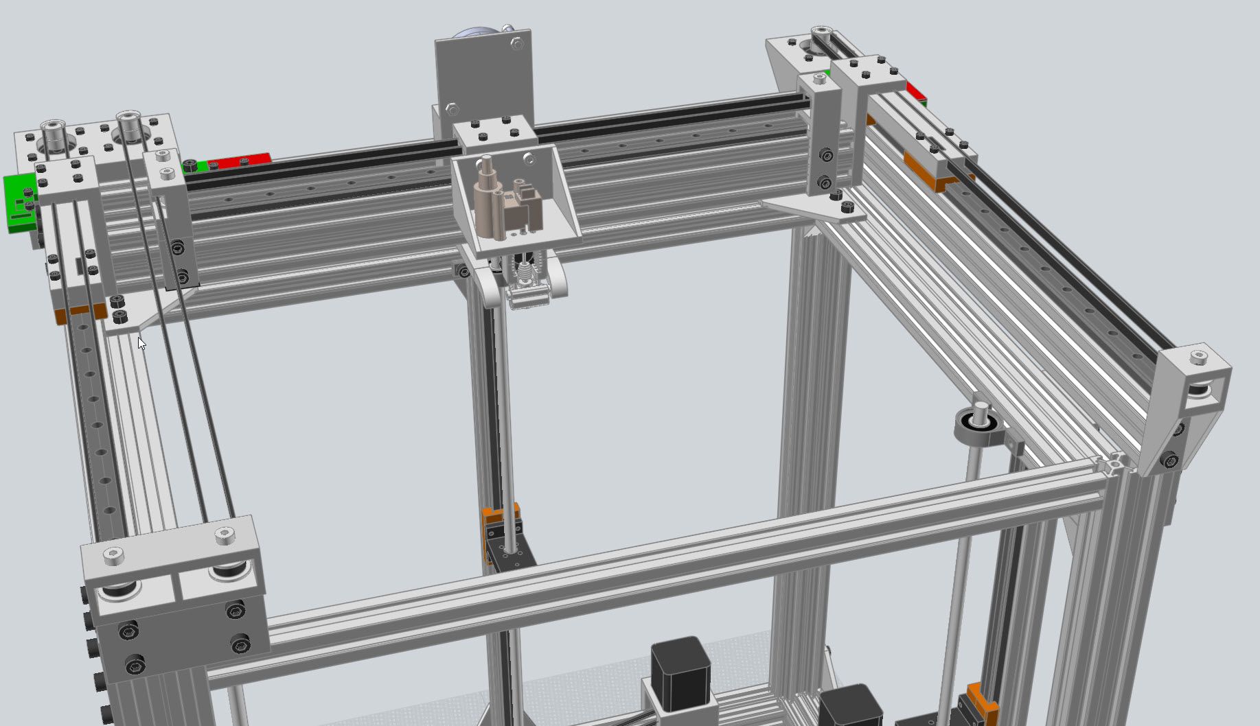
Hi,
Here is the design model I created.
As you can perhaps see on the far left is the Y axis stepper for the left side of the X gantry.
The X axis stepper is just to the right of that.
On the far right is the other Y axis stepper.
You will notice that I have allowed for dual carriage blocks on each Y axis rail.
Printers: a small Utilmaker style, a small CoreXY and a E3D MS/TC setup. Various hotends. Using Duet 3 hardware running 3.4.6
-
Hi,
Well X, Y and Z are up and running.
Sunday should see the three parts printed that will needed for mounting the hotend and BLTouch.
Once the BLTouch is in place some height maps can be generated to see how things are coming along.
If they look good then some test parts can be printed but the part cooling fan will not be in place. The fans haven't arrived and the design of the air ducts is still a work in progress.
Frederick