Endstops. Duet wifi 2
-
Hi All
My endstops do not respond. LEDs are lit when not triggered, when i try to invert them via the config tool or via the the config. file it makes no difference. I have have used every setting i can and could find online, including testing the wiring and switches and replacing switches. Is it my board?
Ps. Its Duet Wifi 2 on an Ender 3 could someone confirm their config. file to confirm Im not doing and stupid even tho I thing I have tried every setting possible.
Thanks
-
What does the m119 command do?
you changed
M574 X1 S0
to
M574 X1 S1
and it made no difference in the output? this should not happen and you prob overwrote the settings later in your config again.you made sure that the switch when triggers with a multimeter that its operating correctly?
post your config.
-
@james3d said in Endstops. Duet wifi 2:
My endstops do not respond. LEDs are lit when not triggered
That's normal if they are normally-closed endstop switches. Use the M119 command to test whether the firmware is reading them correctly. https://duet3d.dozuki.com/Wiki/Connecting_endstop_switches#Section_Test_endstop_switches
-
I am having a similar problem with E0, E1 endstops. They show up as triggered but they aren't, even when there are no endstops hooked to them they show up as triggered.
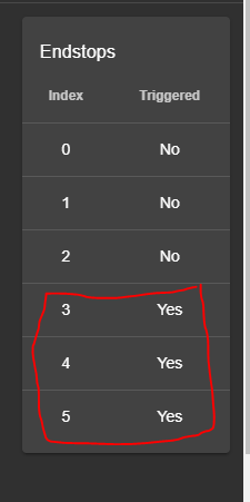
When i hook my endstop to them nothing happens.
M119 shows this

I had everything working fine a few weeks ago but I had disabled my U axis in the config for a while while I was doing some prints. I come back and re-enable U and the endstop for U will not work. All others work fine. I have even tried attaching a different endstop switch to make sure that it was not a faulty switch and get the same results.
; Configuration file for Duet WiFi (firmware version 1.21)
; executed by the firmware on start-up
;General preferences*******************************************************************
G90 ; Send absolute coordinates...
M83 ; ...but relative extruder moves
M550 P"BOXX" ; set printer name
;M584 U9 ; Drive mapping;Z-Probe*******************************************************************
M307 H7 A-1 C-1 D-1 ; Disable heater on PWM channel for BLTouch
M558 P9 F100 H5 R0.2 T6000 B0 ; Set Z probe type to BLTouch and the dive height + speeds
G31 P25 X-3 Y-39.3 Z0.45 ; Set Z probe trigger value, offset and trigger height
M557 X15:350 Y20:276 S20 ; Define mesh grid;Drives*******************************************************************
M584 X0 Y1 Z2:3 E4:5 U9 ; Drive mappingM569 P0 S0 ; X Drive 0 goes forwards
M569 P1 S1 ; Y Drive 1 goes backwardsM569 P2 S1 ; Z1 Drive 2 goes backwards
M569 P3 S1 ; Z2 Drive 3 goes backwardsM569 P4 S0 ; E0 Drive 4 goes forwards
M569 P5 S0 ; E1 Drive 5 goes forwards
;M569 P6 S0 ; NOT USED;M569 P7 S0 ; NOT USED
;M569 P8 S0 ; NOT USED
M569 P9 S0 ; U Drive 4 goes forwardsM669 K1 ; Select CoreXY mode
M350 X16 Y16 Z16 E16:16 U4 I1 ; Configure microstepping with interpolation
M92 X66 Y66 Z1600 E443.62:443.62 U200 ; Set steps per mmM566 X200 Y200 Z300 E1000:1000 U100 ; Set maximum instantaneous speed changes (Jerk) (mm/min)
M203 X30000 Y30000 Z400 E4000:4000 U5000 ; Set maximum speeds (mm/min)
M201 X800 Y800 Z80 E1000:1000 U800 ; Set accelerations (mm/s^2)M906 X1200 Y1200 Z1300 E400:600 U1200 I30 ; Set motor currents (mA) and motor idle factor in percent
M84 S30 ; Set idle timeout;Heaters*******************************************************************
M305 P0 S"BED" T100000 B4138 C0 ; Set thermistor
M143 H0 S100 ; Set temperature limit for heater 0 to 225CM305 P1 R4700 T100000 B4388 ; Set thermistor
M143 H1 S280 ; Set temperature limit for heater 3 to 300C
M307 H1 A934.7 C268.4 D7.9 V24.1 ; Set PID parameters for heater 1M305 P2 R4700 T100000 B4388 ; Set thermistor
M143 H2 S280 ; Set temperature limit for heater 4 to 300C
M307 H2 A796.6 C254.5 D8.6 V24.1 ; Set PID parameters for heater 2;Tools*******************************************************************
M563 P0 D0 H1 F4 ; Define tool 0
G10 P0 X0 Y0 Z0 ; Reset tool 0 axis offsets
G10 P0 R0 S0 ; Reset initial tool 0 active and standby temperatures to 0CM563 P1 D1 H2 F6 ; Define tool 1
G10 P1 X0 Y0 Z0 ; Reset tool 1 axis offsets
G10 P1 R0 S0 ; Reset initial tool 1 active and standby temperatures to 0C;Fans*******************************************************************
;M106 P0 S0 I0 F500 H-1 ; UNUSED
M106 C"T0 FAN" P3 S1 I0 F500 H1 T70 ; T0 HE
M106 C"T0 LAY FAN" P4 S0 ; T0 PCF
M106 C"T1 FAN" P5 S1 I0 F500 H2 T70 ; T1 HE
M106 C"T1 LAY FAN" P6 S0 ; T1 PCF
;M106 P7 S0 H3 T70 ; T2 HE
;M106 P8 S0 ; T2 PCF;Axis Limit*******************************************************************
M208 X0:355 Y0:360 Z0:400 ; Set axis min/max
M208 U0:300 ; Set axis min/max;Endstop Settings*******************************************************************
M574 Z1 S2 ; Set endstops controlled by probe
M574 X1 Y1 S1 ; Set active high endstops
M574 U1 S1 ; Set homing switch configuration for toolchange lock. Both switches should be wired NC and in series.;Resume after power loss*******************************************************************
M911 S21.0 R23.0 P"M913 X0 Y0 G91 M83 G1 Z3 E-5 F1000" -
@james3d See these steps of the Ender 3 guide:
Wiring: https://duet3d.dozuki.com/Guide/Ender+3+Pro+and+Duet+Maestro+Guide+Part+1:+Wiring/37#s119
Configuration: https://duet3d.dozuki.com/Guide/Ender+3+Pro+and+Duet+Maestro+Guide+Part+2:+Configuration/38#s129
Testing: https://duet3d.dozuki.com/Guide/Ender+3+Pro+and+Duet+Maestro+Guide+Part+3:+Commissioning/39#s145
Test homing behaviour: https://duet3d.dozuki.com/Guide/Ender+3+Pro+and+Duet+Maestro+Guide+Part+3:+Commissioning/39#s147Ian
-
@cdl1701yahoo-com I think it would have been better for you to start a new thread. This thread is dealing with a different endstop issue.
What firmware version are you using?
You U motor is connected to drive 9/E6 on the Duex, according toM584 X0 Y1 Z2:3 E4:5 U9 ; Drive mapping. The firmware is reacting as if no U endstop is connected.
Is the U endstop plugged in to the correct header on Duex, E6 STOP? (See https://duet3d.dozuki.com/Wiki/Duex_wiring_diagrams)
Is there a jumper on the ENDSTOP VOLTAGE SELECT jumper?It is normal for defined tools to show their endstops (you have two defined, so two endstops), in case filament sensor microswitches are fitted. If there is no endstop connected, they will show as triggered.
Ian
-
I am creating a new thread for this but I currently have it plugged into the E0 endstop.