@3dmntbighker 
Maybe this will get more peoples attention to answer. 
Best posts made by cdl1701yahoo.com
-
RE: Exturder suddenly will not work with manual extrudeposted in General Discussion
-
RE: Call macro in homez to clear BLtouch faultposted in Tuning and tweaking
@Phaedrux said in Call macro in homez to clear BLtouch fault:
M400
Ahh that did it! Thanks for the help.
; homez.g
; called to home the Z axis
M98 P"/macros/BL_TOUCH/Alarm_release.g" ; Clear any faults
M400
G4 P500
G91
G1 S1 Z10 F6000 ; Lift z so we don't crash
G90
G1 X178 Y176 F6000 ; Move probe to middle of bed
M558 F500 ; Set the probing speed
G30 ; Do a single FAST probe to home Z axis
M558 F50 ; Set slower probing speed
G30 ; Do a single SLOW probe to home Z axis -
RE: Dual gear extruder driveposted in General Discussion
I have had a bondtech QR, Bondtech BMG and the BMG x2 as well as a few clones, I ended up designing and printing my own gear housings and just using the gears from them. The Clone gears wear out much faster than the genuine bondtech gears so now I just buy bontech gears and parts.
I have customized my housings to work with the printer design I am working with rather than conforming to the standard Bondtech designs. I highly recommend going dual gear over single gear, you will not regret it.
Just a side note on the BMG x2, I never did get it working to my satisfaction although that was not a reflection on the extruder but more on the E3D Chimera (genuine). I personally cannot recommend the Chimera/Cyclops as a hotend.
Latest posts made by cdl1701yahoo.com
-
RE: Z axis: ball screws vs beltsposted in 3D Printing General Chat
@mrehorstdmd I am using ball screws with a 300x300x10 bed and they do not drop when the motors are disengaged, but, the bed does move easily when pressed with I would say about a pounds worth of pressure.
-
RE: Parts are coming out too small...posted in Tuning and tweaking
I would first start with making sure your steps/mm are correct in the firmware. One thing you can do if you think you do have them set correctly is to fine tune them with this formula:
A = current steps per mm
B = Actual steps movedA(100/B)
I will use the X axis as an example.
-
- Set your starting position in a spot where you can easily measure between two points on the X axis, if you have calipers even better and 0 out the starting distance.
-
- Tell the printer to move the X axis 100mm and then measure the distance that it actually moved, this will be the "B" number of the formula below. This will give you a new steps/mm that you enter in the firmware.
Repeat the steps for Y axis and Z axis and even your extruder. For the extruder just make a mark on your filament at 110mm above where it enters the extruder once it has finished extruding measure the distance to the mark. Take that measurement and subtract 10, if it is positive you are not extruding enough, negative, extruding to much, zero you are right on.
-
-
RE: Burned up the stepper driver #9 on my Duex5posted in Duet Hardware and wiring
@dc42 Thanks for the help Dc42. The reporting has stopped but the driver is still really hot to the touch so I am going to add a fan to blow across the drivers for now until I can get some replacements.
-
RE: Burned up the stepper driver #9 on my Duex5posted in Duet Hardware and wiring
Also, is there a way to get it to stop sending the warning about high temp?
-
Burned up the stepper driver #9 on my Duex5posted in Duet Hardware and wiring
So, yeah, totally my fault as I had the connector offset by one pin since I was not using the locking type and instead using the DuPont type. This is a good reason to use the locking type as you can't put them on wrong, lesson learned.
So now I am getting a continuous Warning: high temperature reported by driver(s) 9 even though I have changed my config to use driver 8 and commented out the M569 line for driver 9. I am thinking I would like to try to replace the driver but the only ones I am finding are on Digikey (TMC2660-PA-T
) and says it has a 26 week lead time!! Is there anywhere else I can get these and is that the correct driver? -
RE: Modified Laser Filament Monitor layoutposted in Filament Monitor
Yes, I got the missing grounds fixed and there were also some VIAs that were too close to traces so I got all those fixed.
As for the BOM here is what it looks like. For example the 470R resistor on Mouser there are a bunch to choose from how do I know what I should use. Also the sensor I cannot find where to actually purchase it. It could be that I just don't know much about what I am looking at.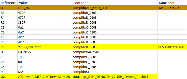
-
RE: Modified Laser Filament Monitor layoutposted in Filament Monitor
Got the PCBs ordered but so far not having much luck finding a BOM for the board. I guess if I can't find one I will just take apart the one that I have and use the parts from it.
-
RE: Modified Laser Filament Monitor layoutposted in Filament Monitor
Figured I would order them from JLCPCB. Got all the design rules to clear but now I am having a hard time figuring out exactly what parts to order. I figured there would be a BOM with part numbers but the BOM data does not have much information.
-
RE: Modified Laser Filament Monitor layoutposted in Filament Monitor
Oh wow that design rule check is a big help. It found some items that were too closet together.
-
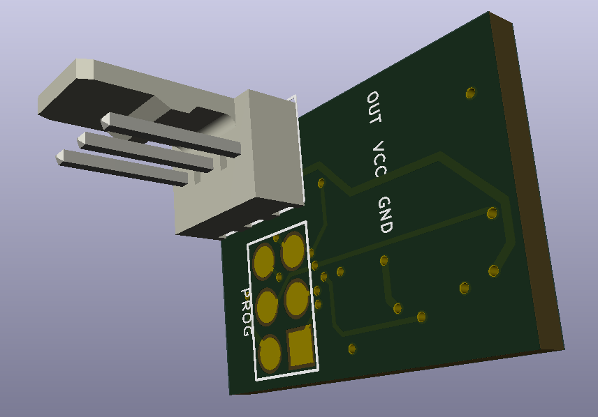
Modified Laser Filament Monitor layoutposted in Filament Monitor
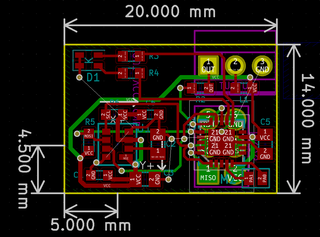
I am working on a new extruder design that I want to be able to incorporate the Laser Filament Monitor into it but the current board layout does not work for my needs. I have modified the KiCad files and wondered if there is anyone who knows what they are doing can take a look at them and make sure that I have the layout correct. I have never done any electrical board layouts before so I am very much a novice in this.
I have decreased the overall size of the board and moved the sensor closer to the edge of the board and removed the two pin connector points that were there.
Here are a few screen shots of what I have done.
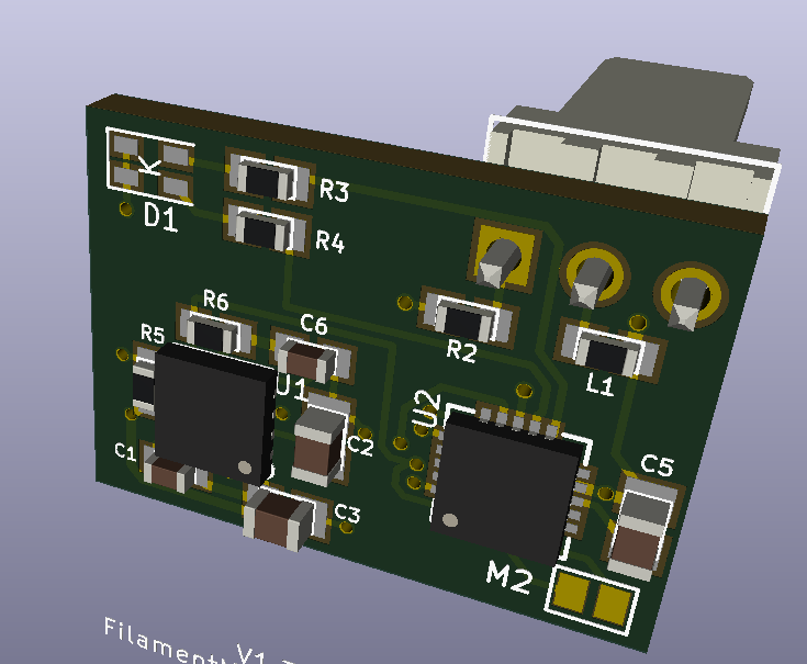
The 3D model shows the connector but I really just want the holes to solder the wires to.
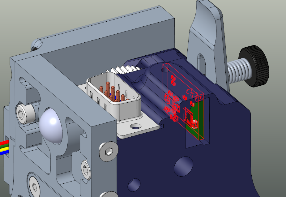
Here is a screen shot of where I am planning on putting the sensor in the extruder.