Markforged Kinematics Troubleshooting
-
Hi,
Well X, Y and Z are up and running.
Sunday should see the three parts printed that will needed for mounting the hotend and BLTouch.
Once the BLTouch is in place some height maps can be generated to see how things are coming along.
If they look good then some test parts can be printed but the part cooling fan will not be in place. The fans haven't arrived and the design of the air ducts is still a work in progress.
Frederick
-
@fcwilt said in Markforged Kinematics Troubleshooting:
As you can perhaps see on the far left is the Y axis stepper for the left side of the X gantry.
On the far right is the other Y axis stepper.
You will notice that I have allowed for dual carriage blocks on each Y axis rail.
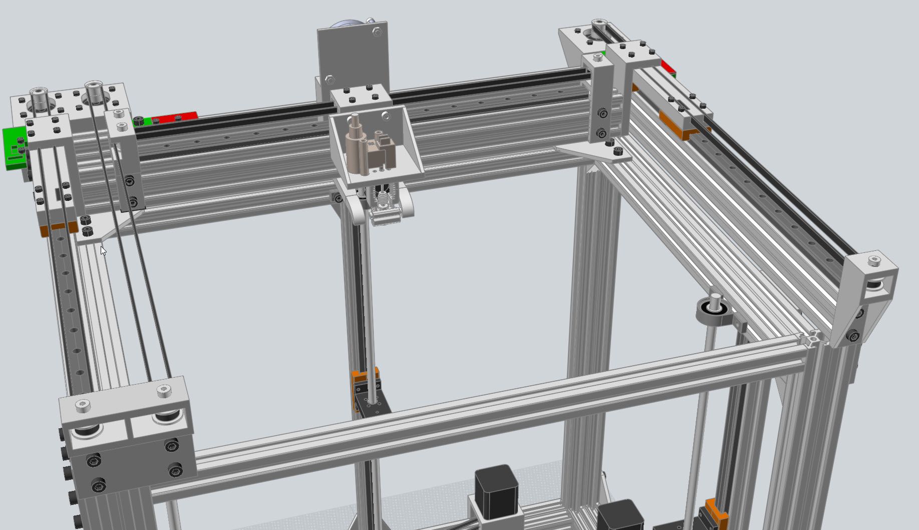
That is pretty much exactly how I envisioned that setup. My design pretty much mimics the Markforged layout to a T, but I hadn't realized until setting the machine up and looking in to that routing path a bit more that racking can be an issue, hence why I ordered some extra carriage blocks and am currently making minor design changes to printed parts.
There is a Markforged Mark Two at my university and when it runs there is no play at all (which was part of my reasoning for using that belt path, and also that it looked easy to physically set up). However, it's X axis is very short, they're using a machined aluminum crossmember, and also two MGN12C carriages on the Y axis side of the gantry. Engineering and creating machines is a learning process and I am definitely learning from this.
-
@Red-Sand-Robot said in Markforged Kinematics Troubleshooting:
There is a Markforged Mark Two at my university and when it runs there is no play at all (which was part of my reasoning for using that belt path, and also that it looked easy to physically set up). However, it's X axis is very short, they're using a machined aluminum crossmember, and also two MGN12C carriages on the Y axis side of the gantry. Engineering and creating machines is a learning process and I am definitely learning from this.
I would imagine if I had a "U" shaped machined metal piece connecting the two pairs of carriage blocks it might work well with just one motor.
However adding the second stepper is straightforward as you can see. Part wise you are only adding a stepper, a pulley, an idler, a belt and the mounts.
Even if I do machine that metal piece I would keep the stepper.
I have exercised both axes over their entire range of motion and detect no binding at all BUT that is with no load on the X gantry.
One thing I have done which is perhaps a bit "odd" - I have mounted the X axis endstop switch to the frame instead of the gantry. This means that I have to home Y and leave it at Y max while I home X. Once they are both homed I can move them as needed. I prefer 0,0 being the center of the bed. The only downside to this is that I cannot, as many folks do, home X and Y simultaneously. It adds a bit of time to the process but given that printing 3D parts is a long process in itself, a few extra seconds homing is not a issue for me.
Today's goal: Get the hotend and BLTouch mounted.
Frederick
-
Hi,
After working some with the X axis I decided it needed a change.
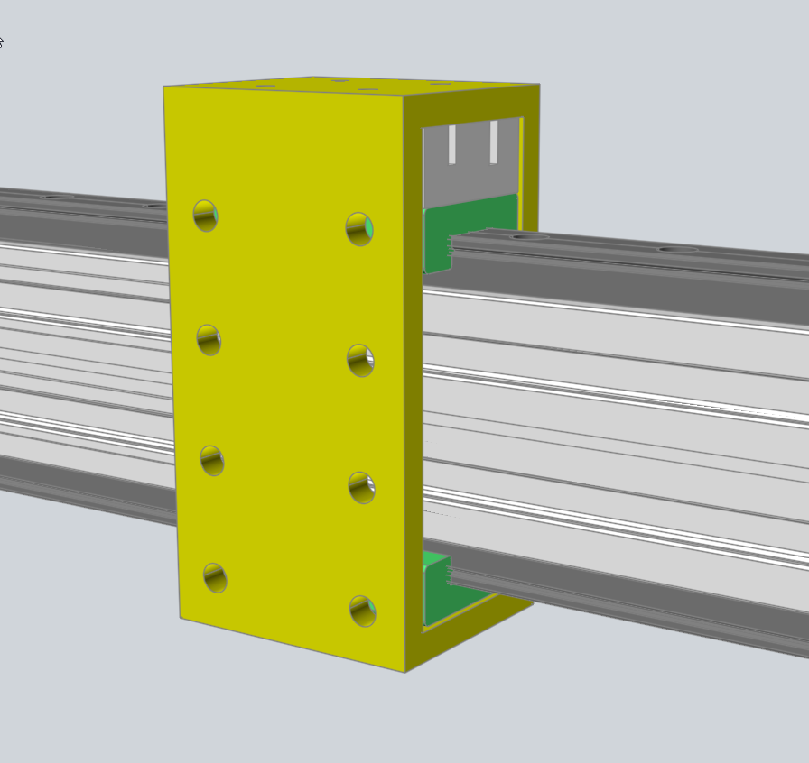
To increase rigidity the X axis rail is supported by a 20x40 extrusion. This means that the hotend has to be positioned some 100 mm down from the top of the rail.
The plastic piece that I printed, to hold the hotend assembly, attached to the rail carriage block and hung down in front of the extrusion.
However the piece had too much flex for my liking.
So I added a second linear rail to the bottom of the extrusion and the plastic piece is now an open rectangle, attached to both the top and bottom rail carriage blocks.
What doesn't show in the image are the M3 brass inserts hot pressed into the holes for attaching the hotend assembly.
It seems much better.
Frederick
-
I attached my carriage to the bottom of a 20x20 extrusion, with the idlers arranged in such a way as to have the belt travel inside the slots of the extrusion. There are covers that attach on top of the blue parts to constrain the bolts holding the idlers. The two heat set inserts on the back are in case of racking still being present, allowing me to implement another motor to drive the gantry in the Y axis (as you have done).

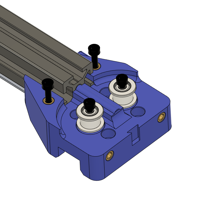
Where were you seeing deflection that made you want to add another linear rail? I would imagine vertical deflection would be nonexistent.
-
@Red-Sand-Robot said in Markforged Kinematics Troubleshooting:
Where were you seeing deflection that made you want to add another linear rail? I would imagine vertical deflection would be nonexistent.
Did you design those parts? Very nice. What program did you use.
I wasn't seeing deflection in the extrusion or the rail. It was the plastic piece that attached to the rail carriage block on the top of the extrusion and then hanging down past the side of the extrusion where the hotend was intended to be attached.
But once I printed and installed the plastic piece I was not happy - too much possibility for flexing.
Now with rails top and bottom I have a general purpose attachment point that is 46mm wide and 88mm tall with 8 M3 inserts on the front and back.
And it is very sturdy - a much better design than my first attempt, which is par for the course.
Frederick
-
@fcwilt said in Markforged Kinematics Troubleshooting:
Did you design those parts? Very nice. What program did you use.
I used Fusion 360 to design the blue, red, and green parts; the white parts are part of the open-source tool changer designed by Joshua Vazquez - designer of the Jubilee tool changing 3D printer. It uses a remotely driven cable to actuate the locking mechanism. Since his design utilizes the CoreXY system I had to modify the attachment point to the carraige.
We're taught SolidWorks at my university but even the student edition isn't free. Fusion 360 is free for makers and hobbyists, and even though it doesn't have quite the capabilities of SolidWorks, Inventor, Solidedge and the like, it is definitely usable. The drawing workspace definitely needs works but as a history based parametric modeler it gets the job done.
@fcwilt said in Markforged Kinematics Troubleshooting:
It was the plastic piece that attached to the rail carriage block on the top of the extrusion and then hanging down past the side of the extrusion where the hotend was intended to be attached.
Ah, the plastic part was deflecting, makes much more sense!
-
Hi,
It's ALIVE!!!
I actually printed a small test piece...
... and discovered that one of the linear rails was too uneven to yield a really good print.
I finally decided to order the better quality units, despite the price, and see how they compare.
Frederick
-
I've been hankering to build a new machine, with a larger bed moving in Z, and an XY stage on top. I'd like it to have space for E3D style tool change. I've looked at various XY layouts; Cartesian (eg Creality Ender 5 and various layouts), CoreXY (lots of 'em), Ultimaker, H-bot and then Markforge. That seems to be most of the styles, unless anyone is aware of more? There's this list.
They all have their pros and cons, and I was slowly coming around to the Markforged layout but with Y motors on each side, like @fcwilt has done, as I feel on larger machines there would be racking issues if one side wasn't driven. The original Markforge machines seem to have a longer Y axis, and a short X axis, so probably don't need the other Y side driven.
However, I then saw this old thread on the reprap forums, which showed a 'double Markforged' layout by user Sangthip:
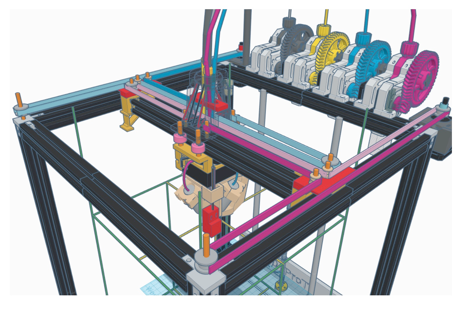
However, his solution won't quite work. On page two, user prot0typ1cal shows how to fix it:
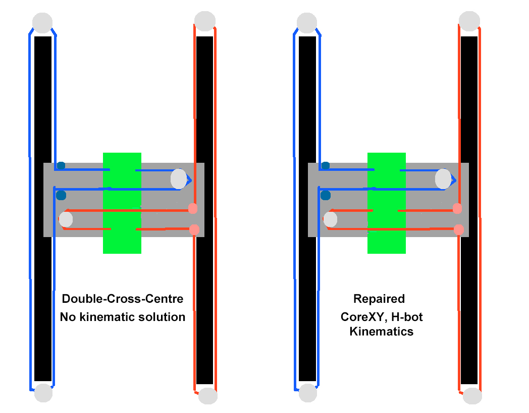
The one on the left is the original layout, which doesn't work.
But the one on the right is, basically, a CoreXY, but with the belt cross moved to the gantry. It should be balanced, like a CoreXY, but with a layout that frees up both ends. I'd looked at the Jubilee, but felt that the belts look unnecessarily long and complicate the tool changing rack, and have noticed similar in other CoreXY builds.
This 'DMF' (for Dual MarkForge) layout does solve a number of problems:
- Like all CoreXY's, it has a balanced pull on the X and Y axes (no racking like H-bot, Markforge).
- Like CoreXY, only two motors, with both of them stationary, unlike Cartesian and other Markforged builds with two Y motors
- Like CoreXY, motors move the same mass (unlike Cartesian and Markforge)
- Possibly a more compact layout than CoreXY, with easier belt path.
- Belts can run behind each other on the X gantry, or be stacked
- Both ends of the Y carriage are clear for tool change posts, on each side of the gantry (this is a big advantage in my eyes)
- Uses the same number of idlers as CoreXY, and roughly the same belt length
- Just looks neater and more refined than CoreXY! (Ensue flame war!)
There are two main issues, as far as I can see:
- extra space needed on X axis for belts (can be mitigated with good design)
- the belt goes through more 180º turns on idlers than CoreXY, so there may be more belt drag. CoreXY has 1x180º turn (around motor) and 4x90º turns (around idlers). DMG has 3x180º turns (motor, 2x idlers) and 2x90º turns. Do you think this would cause a problem?
There's also a crazy double H-bot build in the reprap forums thread, but that just looks... crazy!
Anyway, I'm quite excited by this, and plan to mock up a model of it. Anyone got any thoughts?
Ian
-
Hi,
When considering a more complex design the question always is: Are the benefits enough to justify the extra complexity?
One of my reasons for scrapping my DBOT and trying a MF was to reduce complexity.
IF I had the space I would love to be able to build two essentially identical machines in two different kinematics (say a Dual-Y MF and the Double MF) and then be able to compare the actual results of printing.
So far my simple FT-5 (a Cartesian) has produced the best prints but that may because it is all metal, with the exception of things like endstop mounts printed in plastic.
I find your Double MF design intriguing and I hope you build one and report on your progress.
Is that design you posted using Bowden tubes?
Thanks.
Frederick
-
@fcwilt said in Markforged Kinematics Troubleshooting:
Is that design you posted using Bowden tubes?
Looks like it, though I think it was just showing the concept. I'd stack the belts on top of each other, as then the pinch point for all the belt on the X carriage is at the same place. With the X belts side-by-side, I think it would cause racking in the X carriage.
I take your point about simplicity. And you're right; a well-sorted Cartesian prints really nicely, with short belt paths and a manageable amount of weight on the axes. Delta printers seem to have fallen a bit in popularity, perhaps because they are difficult to set up accurately. CoreXY does seem to be the dominant platform in bed-moving-in-Z machines; I guess I'm just trying to see if there's anything that improves on that design. Otherwise I'd probably buy a FT-5! Might still do...
Ian
-
How hard is this setup to calibrate? I am also planning a big 500x500mm printer with toolchanger and markforged kinematics with dual Y and one X.
-
I have dual Y steppers plugged in to the Z-axis stepper port, with the X plugged in as normal. Only thing I needed to do to get the kinematics to work correctly was to invert a number in the motor matrix. Without the second Y-stepper racking was very severe.


-
@Red-Sand-Robot
Beautiful build! A lot like how I want to do it.
I was thinking of calibrating the steps per unit of the X axis in regards to Y to get it completely square.
Because when moving Y axis you need X axis to be stationary but X stepper has to move with it, needing belts and such to be perfectly equal.
I use this calibration cross to check on my CoreXY:
https://www.thingiverse.com/thing:2484766