monitoring mesh bed compensation level
-
Thinking about it some more, I am pretty sure the printing is happening in a probed area. The print currently running has another 5 hours or so to go at which point I can measure thicknesses and try to measure the gap between nozzle and print bed at various positions. I was hoping that a display of 'actual' Z height rather than 'corrected' Z height would easy the trouble shooting if it was available somehow.
-
To my understanding (and confirmed with trial and error) the polarity is correct. The probe is to the front of the nozzle (negative offset) and to the left (negative offset)
From config.g: G31 P25 X-13.5 Y-34.81 Z2.65 -
Related question: Suppose my z speed/acceleration/jerk value are too low. Would the Duet slow down x and y so as to not exceed the speed limits of Z or would I see what I am seeing now ? I am assuming x and y would slow as needed but thought I better verify that ....
-
@jens55 Yes. Any print move will be capped to the slowest speed of either XYZ or "E" if any of those speed limits are reached. So a very low maximmum extruder speed setting would also affect the overall speed of any move.
-
@jens55 said in monitoring mesh bed compensation level:
Related question: Suppose my z speed/acceleration/jerk value are too low. Would the Duet slow down x and y so as to not exceed the speed limits of Z or would I see what I am seeing now ? I am assuming x and y would slow as needed but thought I better verify that ....
If your Z axis jerk were too low, you'd see stuttering in X Y movement as it tries to apply the mesh compensation.
-
I have confirmed that the model that gave me issues was only printing in the probed area.
I have also confirmed that the mesh is applied to compensate nozzle height although I do not know if the compensation is sufficient.
Measuring the gap between nozzle and glass plate is anything but consistent over the build area.The options I am left with - insufficient compensation for some reason or other or, more likely, incorrect mesh height sensing.
I will scan the bed multiple times at the same temperature and compare measurement points to see if anything jumps out.
-
What settings are you using for the BLTouch? There are some tweaks you can implement to make it more reliable and repeatable.
-
Um ... settings ? I am not aware of any settings for the BLTouch other than trigger height which is set at 25
-
More questions than answers .... attached are three bed maps run consecutively with nothing changed. Each run is 100 points I think. A quick perusal shows that the height can be different on different runs by more than 0.1 mm which is not acceptable to me. I do not know if this is a limitation of a BLtouch (comments ?).
Note that I did not reset z zero between runs!If I measure the same spot ten times in a row (this is without moving x or y, I get the following:
-0.034 -0.034 -0.037 -0.034 -0.029 -0.034 -0.037 -0.037 -0.034 -0.034, mean -0.034, deviation from mean 0.002 ... this is perfectly acceptable
The second run of the same 10 points shows as:
-0.054 -0.051 -0.066 -0.066 -0.059 -0.061 -0.059 -0.054 -0.054 -0.061, mean -0.059, deviation from mean 0.005
The third run shows as :
-0.056 -0.054 -0.056 -0.059 -0.054 -0.056 -0.054 -0.049 -0.051 -0.054, mean -0.054, deviation from mean 0.003
In each case the 10 measurements are taken successively at the same spot without changing x or y but there was a 'home' command between each of the 3 runs of 10 where Z was reset and x/y axis moved.At this point I do not know what to think. Am I expecting too much ? Is the accuracy of the BLTouch acceptable? Why is there so much of a difference in the three bed scanning runs ?
-
What do you have in your M558 command?
https://duet3d.dozuki.com/Wiki/Gcode#Section_M558_Set_Z_probe_type
Here is my BLTouch config for example.
M558 P9 H3 F60 T6000 A10 R0.75 S0.003 B1 ; P9 for BLTouch, dive height 3mm, probe at 100mm/min, travel 6000mm/s, up to 10 probes, pause 0.5s, heaters offThe BLTouch can benefit from a slow dive speed as well as a brief pause between moves to allow the probe to settle. I've also tightened the tolerance for acceptable deviations between probes. So two consecutive probe results must be within 0.003 of each other, and if not, it will reprobe up to 10 times. It also disables the heaters during probe moves to remove any potential interference.
-
M558 P5 H5 F500 T4000 X0 Y0 Z1 which is taken from the Duet setup instructions
Note that if I measure the same point multiple times the readings are ok. It's only when I move x and y between readings do they start to go out of whack -
I suggest you try my config line then. Yours is rather out of date. P5 is for generic switch type probes. P9 is specific to the BLTouch. The X Y Z parameters are also deprecated. And your dive speed of 500 is too fast for the BLTouch.
-
Thanks, I will re-run everything and see what happens.
-
Slight change, I need to run with the bed heater on since the bed changes substantially between cold and operating temp.
I will report back. -
If you preheat the bed, the B1 parameter will only disable the heater for the probe move portion and resume heating after. It should be able to maintain close to the set temp.
-
Oh, ok ... I will leave it as is for now and see how it works out. This is going to take some time
")
I normally run with a 441 point mesh bed when everything is working as it should. Based on the speed so far, it will take the better part of two hours to do the full run !
Just finished the first 100 point scan, 2 more to go! -
@jens55 that seems like overkill for a mesh sequence. When set up, the BL should be able to generate a stable mesh with far less. If we take a Prusa for instance - even on the 9 x 9 set up from a factory configuration takes less than a minute (albeit a different style of sensor).
Is there a specific reason you're running such a dense mesh probe area? If there is a single probe with magnetic interference in the hour of probing (without safeguards like Phaedrux has mentioned) it will show up as a high or low point on your heat map and the entire mesh run is useless, the printer will use what data it is given so an extreme outlier created by an incorrect probe will mean the printer will compensate accordingly.
Do you have a screen shot of your terrain or heat map?
A method I tend to use when I set up new printers is to start with less probe points and add more as you build a solid foundation map.
If you start with, say 4-8 points in total and get the deviation low, then 8-12 and get it low again etc etc you will save lots of time and remove the almost certain introduction of error in a 441 point scan. -
I run a 500 * 500 bed so I find the more data points the better. I too start out with 4 points and go up from there
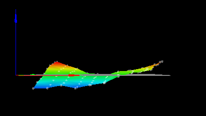
I now have 2 height maps with the new settings and multi probing. The difference between data points is down to a maximum of about 0.03 mm so that is an improvement.
-
The new parameters for the BLTouch help. I will see how it works out in real life with a 441 point mesh map and gauging the gap between the bed and the nozzle.
Here are 4 runs of 10 probes. Again, no x/y movement between the 10 data points but full z home between the 4 separate sets of data points.
-0.054 -0.055 -0.051 -0.053 -0.051 -0.053 -0.053 -0.050 -0.050 -0.049, mean -0.052, deviation from mean 0.002
-0.047 -0.047 -0.043 -0.045 -0.043 -0.043 -0.043 -0.043 -0.042 -0.040, mean -0.043, deviation from mean 0.002
-0.048 -0.050 -0.048 -0.044 -0.044 -0.044 -0.045 -0.043 -0.042 -0.040, mean -0.045, deviation from mean 0.003
0.045 -0.044 -0.044 -0.042 -0.043 -0.039 -0.035 -0.035 -0.033 -0.031, mean -0.039, deviation from mean 0.005Note that these figures are better than the differences seen between the mesh maps.
-
The results are in and I am not impressed. Checking the first row that was probed, there is a difference of bed to nozzle distance of 0.25 mm from one side to the next (with mesh correction active!). The previous version with a faster and single probing showed approximate;y 0.35 mm difference between one side and the other so it is an improvement but it literally took 2:00 hours to run the scan.
I am expecting the nozzle to bed difference to be a maximum of 0.05 between any points on the bed but would prefer 0.002 mm. In any case, I am a long way from a satisfactory mesh bed scan
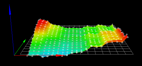
heightmap(3).csv