@T3P3Tony, Thank you for keeping the forum. Discord has it's place but loosing the forum would be very bad IMHO. I agree with your two reasons to resist a move to Discord. I do utilize Discord but it is another tool and another approach at a community but should never be considered as a replacement.
Thank you for all your hard work!!!
Best posts made by jens55
-
RE: RepRapFirmware Discordposted in General Discussion
-
Merry HO HOposted in Off Topic
Hope you are all having a very happy Christmas (or whatever else you celebrate). Stay safe !!
A special THANK YOU to everybody at the DUET team for your incredible service both in the design and especially the support !!
-
RE: I'm confused about stepper motor voltageposted in Duet Hardware and wiring
Steppers are current based devices. Although general specs usually list a voltage, it is irrelevant for your purposes. When a stepper driver switches on a phase, it measures the current that is drawn by the motor and limits that current.
Since the phases of a stepper motors are coils of wire, they have inductance (which is also listed in the spec's). When you switch on current to an inductor, the current flowing will not go to full current flow but rather the current increases at a given rate based on inductance and voltage. In order to increase speed, you need to be able to bring the current up to the rated current as fast as possible. Higher supply voltage will do that for you. A 12V power supply will supply the same rated current but will not do it as quickly.
Since a stepper motor works by switching on (and off) current in two windings, a higher voltage can substantially increase your speed.
If you ever look at the speed vs torque curve on a stepper, you will see that torque decreases very quickly as the motor speed goes up. This is simply because the drivers can not supply instant current and it takes longer for the current to reach the rated current if the voltage is lower. So, if you happen to trip over a graph plotting torque vs rpm at different supply voltages, you will see that a higher voltage power supply keeps the motor torque higher at a higher motor speed (because rated current is reached quicker).
A side note - the maximum torque a motor can develop is based on it's construction and current handling capability but there is a given maximum. Torque will basically remain at that maximum until the on/of/on switching of phases gets too fast (net current through the coils is reduced because it takes a finite time to go from no torque to full torque). A higher voltage power supply can force the current to rated current faster than a lower voltage power supply.Not everything in that rambling reply might be correct but the overall gist is correct.
-
RE: PETG as support for PLAposted in 3D Printing General Chat
I just finished a test print with 100% success. Thanks for the suggestions.
I think the major problem was that I never removed the gap from when I was printing both the model and support with pla. I had completely forgotten about this.
I also printed slower although I don't actually know which of the many speeds is used - I suspect it was 26 mm/sec for petg and pla at 40 mm/sec.
The petg and pla stuck together to a limited degree ... enough to hold everything together yet not so much as to make support removal difficult.I only have two words ...... Woooooo Hoooooo !
-
RE: Meta commandsposted in Gcode meta commands
@alankilian, I REALLY appreciate any and all help and I apologize if you felt in any way slighted whatsoever. It was most certainly not my intent !!!
I got confused by the sentence "The point of continue is to skip an iteration."
DanS79 cleared it up and confirmed my interpretation by saying "To be clear it doesn't skip an iteration, it skips everything after the continue statement in the current iteration." IE it doesn't skip an iteration but goes back to the beginning of the loop.
Your example (thanks) did however clarify another point on the continue command that I was not aware of and hence my earlier confusion about sequential 'if' statements. The iteration happens over the 'while' loop and not as I had assumed over the 'if' loop. A very important bit of learning for me!
So to repeat, I apologize profusely and hope we are back on the same wavelength ! -
RE: Why I went back to RRF2posted in Example setups and prints
Moderators .... could we please lock this thread and stop with the negativity please ?
-
RE: Duet tool board extruder weakposted in Duet Hardware and wiring
Wow, what a ride ..... I am happy (more like ecstatic) to report that after correcting my config.g (thanks again @gloomyandy ) the printer completed both a pressure advance test and a temperature tower without any complications whatsoever !
I did an M122 Bnn and nothing seemed out of the ordinary ... but then the prints came out just fine so there shouldn't have been anything odd to report. -
RE: Auto bed compensation working just not very wellposted in General Discussion
If your offset values are zero, you are probing points that the Duet doesn't know about and you are then taking those probing points to adjust the mesh height. You are creating a bad height map and then applying it.
I don't understand how you can possibly expect any results but crap. You might as well work without any height map.
It's odd that you get stripes but before anyone can give you any suggestions about what is wrong, you MUST set things up properly !!! -
RE: Yet another heater fault issueposted in Using Duet Controllers
I am happy to report that the issue seems fixed. The printer has been going for a bit over an hour and nothing untoward has happened (knock on wood). Hopefully it's because I replaced the connector rather than just having moved things a bit and re-establishing a good connection.
I can't believe that the first connector I replaced was the dud one - I fully expected to replace each and every connector with the last one being the problem ....It amazes me how quickly things went from a bit of a jumpy temperature graph to a single heater fault to 8 or so faults on my last print.
BTW, for a 215C set point, the temperature fluctuates between roughly 214 to 216 with the vast majority being between 214.8 and 215.4.
-
RE: Slow down before endstop?posted in CNC
Another method that is often used with CNC mills is to allow the switch to be bypassed. Instead of the carriage directly activating the end switch, the switch is mounted to the side and a lever is used to activate it. The carriage approaches the lever and depresses it which activates the end stop switch but there is no hard stop so if it takes a mm for the carriage to stop, nothing is harmed.
You could use a micro switch with a lever with a roller on the end and have a protrusion on the carriage that activates the lever without running into a stop.
Hard to explain but very simple and effective.
Latest posts made by jens55
-
RE: Software bundle 3.6.0 stable released!posted in Firmware installation
@dc42, just a quick comment ... when upgrading from 3.6.0-rc1 to 3.6.0 I had several pop ups of incompatible versions. Also, the initial upgrade did not apply the upgrade to my MB6HC board. A second run of the upgrade package did eventually upgrade the MB6HC board as well.
-
RE: Heater faultposted in Tuning and tweaking
@ianborg I would look into possible interference somewhere but I can't suggest where to start looking.
Alternatively, as a band-aid, set your printer up to only start heating the nozzle when the bed is at temperature. -
RE: Heater faultposted in Tuning and tweaking
@ianborg, I have similar issues with a nozzle heater. It generally boils down to poor connections either at the heater end, temperature sender end , at the controller end (rare) of either or, as in my case, a plug/socket connection in the line (so I can swap out either without a major effort).
Looking at the temperature curve can usually give you a good hint on where the fault lies. The bed can't change temperature fast so if you see a fast temperature change the issue is in the temperature sensing circuit. If it is a slooow temperature change then it's likely to be the heater.
Last but not least, at least in my case, there is a good chance the sensor itself is faulty or getting towards it's end of life.
Good luck! -
RE: Suggestions needed to fix a poor printposted in Tuning and tweaking
Just as a follow up, I am happy to report that drying the PETG helped quite a bit. While the new print isn't perfect, I can't call it a 'dogs breakfast'. Besides drying the filament, I also went with random seams as all other choices ended up putting the seams on the overhangs.
-
RE: Suggestions needed to fix a poor printposted in Tuning and tweaking
@jay_s_uk, thanks, I might give it a try if things don't improve with the dried filament. I will do another print tomorrow morning.
-
RE: Suggestions needed to fix a poor printposted in Tuning and tweaking
@jay_s_uk, I have had bad luck with beta builds before and I was waiting for 3.6. I was aware of the improvements and was looking forward to 3.6 being released to try that out.
-
RE: Suggestions needed to fix a poor printposted in Tuning and tweaking
@engikeneer, thanks for that suggestion - no the PETG was not dried and yes, I have seen the difference in print quality but for some reason it didn't occur to me to try that. I will dry it overnight and try again tomorrow.
On the ABS, I have very little (practically nil) cooling and it is an enclosed printer. I could see two sides being good and two sides being bad if it was a fan issue but why would only one side turn out nice?
I will check on the seam ... again something I didn't think of checking!
-
RE: Suggestions needed to fix a poor printposted in Tuning and tweaking
@jay_s_uk, 3.5.1 for both printers.
-
RE: Suggestions needed to fix a poor printposted in Tuning and tweaking
@jumpedwithbothfeet, thanks! I did notice the ringing but I was more concerned about the crappy three other sides. I was thinking that pressure advance would cause the ringing because that is something I have been struggling with. I can't understand how one side could be nice and crisp but the other sides are crappy. The print orientation was with the left end sitting on the build plate so I was expecting all sides to have more or less equal print quality. Also, this is the print from a second printer with the first printer producing crap on all four sides. It is likely that both printers have more or less equal settings (other than what is required for the different filaments) so I was thinking that parameters would be a better explanation.
I will verify that everything is tight. -
Suggestions needed to fix a poor printposted in Tuning and tweaking
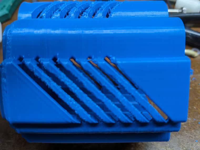
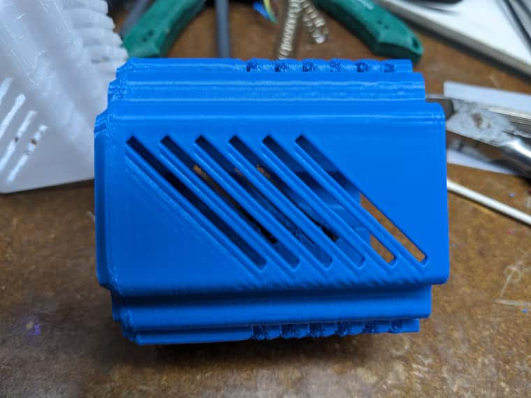
I have had some issues with print quality but they were never enough to really worry about. Yesterday I printed a particular part on my Jubilee printer in PETG and it came out very poorly. I turned around and printed the same part in ABS on a CR10 based printer. One side came out reasonable but 3 sides were crap. Here are the pictures of the ABS print of two different sides. PETG print was even rougher looking (on all 4 sides)
Off hand I have no idea of what I could try to change in my settings to improve the print quality and I could use some suggestions.
BTW, I use PrusaSlicer.2.9