Interested in using two Z axes
-
Many thanks, this sounds like a great solution. I will get to work now.
-
If the motion is just a few mm, could this not be accomplished with a servo?
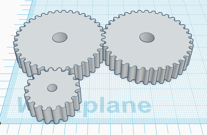
I would maybe drive two Z screws with a single motor, and use a bearing to allow the Z nuts to turn. Put gears on the nuts to mesh them together, and use a servo to drive the gears. When the servo rotates, the nuts turn in opposite directions, moving one head down and the other up. The gears would only need 1/4 turn range (Assuming T8*8 Z screws) to give a 2mm range, making for a 4mm difference between the two extruder heights. It seems like unnecessary complication to keep track of 2 different screws, and a potential to have things drift out of synchronization.
A servo can have a relatively binary position, and even in the event of power loss, it will go to either one or the other position.
Only a portion of these are actually necessary to get the required differential between the two heads, as I said, a quarter turn would achieve 4mm.
-
@supraguy Many thanks for these insights. I will admit to having no experience working with servos - having always used stepper motors in the context of 3D printing. I will look into this as well with some students in engineering (I am an artist/teacher who ended up building printers).
Each Z axis weighs a lot - not sure if that matters - I would guess there are various size servos and some can carry a lot of weight. The print arm is made of aluminum and it carries a large tube of dense heavy clay. I have attached an image of the single extruder version.

-
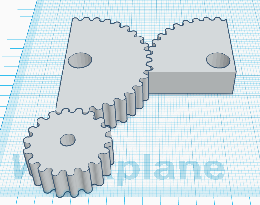
The servo need not carry any weight at all. In this case though, the bearing that allows the gears to rotate will need to bear the weight. Since the servo would be raising one, and lowering the other, it should only ever have to lift a difference in mass between the two. It would also be using the mechanical advantage of the lead screw in that (Plus a 2:1 gear reduction if it's as per the diagram that I have here.)
This would have the gears being attached to the Z lead screw nuts along the large holes in the centre. The gears would then attach to the extruder gantry via a bearing that would allow rotation.
When the servo (Attached to the small gear) rotates, it would turn the two large gears. One of these would raise by 2mm and the other would lower by 2mm.
One drawback to this is that the gears would be relatively large, to span the gap between the 2 Z screws, and there would need to be room to allow this for the towers, however, you might be able to make those gears smaller if for example a smaller difference in height is acceptable, and you only need 1/8 of a revolution instead of 1/4.
This might be overcomplicated as well, and a simpler see-saw configuration balanced on a single lead screw tower might be enough. It would certainly be easier to build.
-
On another note, the clay extruder is brilliant, I love it. I assume that the resultant prints would be kiln fired to make ceramic objects. Do you find that there is any issue with trapped air in between extrusion lines/layers?
At one point, I was looking at trying to extrude paraffin wax in order to do lost wax casting of metal objects, and thought of something like this as an alternative to a pellet hopper extruder which just doesn't seem to work tot he same kind of tolerances that I'd like.
-
@supraguy Many thanks! Yes, the pieces get fired, glazed, etc. We use typical clay you might use for pottery making or sculpture from our ceramic studio. The material is incredibly cheap, so we are looking at scaling up a lot. No problems with trapped air - usually those issues in clay have more to do with excessively thick clay that is unable to dry properly. With printing we can be super specific about wall thickness. If you are interested here's a bunch of objects made with this tool: link text . . . and a forum with tons of info on clay printing: link text
Many thanks again!
-
Clay printing is so cool. I'd love to get my hands on one. Thanks for the links.
-
@dc42 It has been a year, but I am finally ready to implement this design of a printer in which the bed moves on the X and Y axes and there are two independent Z axes each with an extruder that can move up a bit to get out of the way. I am interested in following your suggestion that:
"using M584 commands in the tool change files. You would assign both motors to Z, also assign the individual motors to U and V axes, but hide the U and V axes using the P parameter in the M584 command. When selecting a tool, un-hide U and V, move U or V down a few mm to lower the tool, then hide U and V again. When freeing a tool, do the same except move U or V up the same distance."
Does this still seem like the best approach?
I'm going to get to work testing this finally, and I'll hopefully be able to share the results of this experiment soon.
Last Spring I experimented a bunch with a dual nozzle clay printer that did not move independently, which was fun - but I believe the nozzles "see-sawing" up and down will improve the quality of the process a lot. If anyone is interested in the fixed nozzle dual color clay experiments, I wrote them up here: https://wikifactory.com/@tom/stories/dual-color-clay-printing-experiences-spring-2019 -
Two steppers, each defined as an axis, and g-code to manipulate them is well within the capabilities of Duet/RepRap.
Mechanical swapping between the two extruders based on a single servo or stepper seems a very predictable approach as well.
There is probably no "right" or "wrong", and maybe not even a "better". It is much more a philosophical choice based on what YOU like.
Me, personally, I'd do the two stepper/axis/g-code thing. That's because I am very comfortable with Duet/RepRap configuration in specific and G-Code in general. I can see where a person who was more comfortable with mechanics (than code) would go the other route.
-
@tom_lauerman said in Interested in using two Z axes:
Does this still seem like the best approach?
I'm going to get to work testing this finally, and I'll hopefully be able to share the results of this experiment soon.I think that approach should work well, but I have not tested it.
Duet WiFi hardware designer and firmware engineer
Please do not ask me for Duet support via PM or email, use the forum
http://www.escher3d.com, https://miscsolutions.wordpress.com -
@dc42 Many thanks everyone, I understand how to do this a little better due to the wonderful Duet Gcode documentation available, specifically this and this. I'm travelling for the holidays presently, but hope to test this on the machine I have built with two Z axes very early in the new year. I'll share when I do.
-
A belated Happy New Year!
Happy to say I'm making progress with this build. I've completed designing/constructing the hardware, updated to firmware version 3.0 and I have the two Z axes both moving beautifully in a synchronized fashion. I have also mapped the two Z motors to axes U and V as recommended. What I'm stuck with presently is how to hide the U and V axes. I've read over the documentation on the M584 command, but the U and V axes keep showing up on my web control interface despite a few klutzy attempts to hide them. Wondering if someone can clarify how to hide the U and V. Here is the line I use to set the drives (each tool uses two extruder motors):M584 X0 Y1 Z2:7 U2 V7 E3:4:5:6 ; set drive mapping

-
@tom_lauerman M584 P3 will show 3 axes so will hide U and V. M584 P5 will bring them back.
-
@deckingman That worked wondefully. Many thanks for your prompt response and suggestion. Now to implement the hiding/unhiding in the tool change process to get the "teeter totter" going . . .
-
@tom_lauerman Glad to help. It's how I individually home my CoreXYUVAB before combining the axes back to simply CoreXY.
-
OK, so now I've successfully hidden the U and V axes ( thanks @deckingman !), and the machine is switching from tool 0 to tool 1 when expected, but not executing the "teeter totter" effect I am going for in which the tool moves up or down when not in use. For example, I tried using these tool change scripts:
; tpost0.g
; called after tool 0 has been selected
M584 P5 ; unhide U and V axes
G1 H2 U-5 F6000 ; lower U (right tool) -5mm
M584 P3 ; hide U and V axes again; tfree0.g
; called when tool 0 is freed
M584 P5 ; unhide U and V axes
G1 H2 U5 F6000 ; raise U (right tool) 5mm
M584 P3 ; hide U and V axes againBut the tool did not move up or down, just functioned like a standard (non teeter totter) dual extrusion setup.
Any insights would be much appreciated!
-
@tom_lauerman With all the axes visible, what happens if you nudge U and V via the web interface? Or alternatively, what happens if you send the commands in the tool change macros one line at a time?
-
Thanks for the suggestion @deckingman , I tried the first approach you mentioned, nudging the U and V with all axes visible. This gave some surprising results. It seemed that both U and V were able to move independently, however, not at all at the speed or distances one would expect. So if I tell V to move up 5mm it might only move up 1mm or less. Same with U.
Curiously, with axes unhidden the Z axes no longer functions correctly. I ask it to move up or down and it does not. When I hide the UV again, the Z works fine - tell Z to move 10mm up or down and both axes move up or down 10mm.
I got the sense that the order I tried things in mattered too, that possibly sending a command to U or V had a negative impact on the functioning of Z, but I'm not sure about that.
I was not sure if I needed to input all the information for these "phantom" axes, such as microstepping, motor current, steps per mm, etc. I tried it both ways (with all that info supplied for U and V, and without) with similar results.
-
@tom_lauerman said in Interested in using two Z axes:
Curiously, with axes unhidden the Z axes no longer functions correctly. I ask it to move up or down and it does not. When I hide the UV again, the Z works fine - tell Z to move 10mm up or down and both axes move up or down 10mm.
I can understand that. The firmware calculates the positions for the motor in order. So it first calculates the U and V motor positions needed to position Z correctly, then if the U and V axes are not hidden, it recalculates them for the correct U and V positions. However, when U and V are visible, I would expect you to be able to nudge them by the correct amounts, assuming you haven't messed with the Z axis microstepping (because that would reprogram the U and V motor drivers with the new microstepping).
Duet WiFi hardware designer and firmware engineer
Please do not ask me for Duet support via PM or email, use the forum
http://www.escher3d.com, https://miscsolutions.wordpress.com -
Thanks @dc42 . I double checked and confirm that the U and V are moving at different speeds and distances when operated independently versus when moved together as "Z". Also, if I move U and V independently for awhile they no longer move in a synchronized fashion as part of Z.
Of course, before I can move anything I have to Home Z and U and V. Could there be something in the homing routine that causes an issue? I am using a simple G92 Z0 command to set home for Z, and a similar command for U and for V. Without homing first of course nothing will move. I have no endstops or probes setup on these axes at this time.
I put the M584 P5 command on its own line and the Z operation works better with all axes visible - still having the U and V issues mentioned above. Here's how I have it set up presently:
M584 X0 Y1 Z2:7 U2 V7 E3:4:5:6 ; set drive mapping
M584 P5 ; show all drives (XYZUV)