Problems with mesh compensation using DC42 IR probe
-
Hi everyone! Me and my buddy modified a Sharebot NG printer and we are running Duet2 electronics .
Lately we decided to install the IR probe with a custom mount designed by me.
We are running a 91 point mesh using G29 command. We calculated the Z offset and got a 2.76.
The problem is that it seems the mesh is not correctly working. The first layer is very inconsistent , we get part of the print too close to the bed and part of the print too high .
.
We measured the probe offset but we have no idea how to do it correctly. how do you mesure it? where is the actual focal point of the probe so we can set the correct offset from the nozzle?
Another thing is the fact that the mesh is very inconsistent, we have a lot of devation even tho the bed is pretty flat. We are using the magnetic Build Tak kit (black version) is it good?
Then we are scratching hour had with the z datum, what is it' we are runnung it before G29 and again befor the G29 S1 in start gcode. Is it correct?Thanks in advance.
-
@TaDDragonZ Can you post your config.g and a screen grab of the mesh that is generated? This should tell us a lot about the problem. Also send M115 to the Duet and post the response (this checks the firmware version). Using Buildtak should be okay, but if it probes directly on a white are (eg white text on an otherwise black surface) it may trigger sooner that at other points. It's better to have a completely matt surface, though this might be what you have?
See here for setting the probe offset: https://duet3d.dozuki.com/Wiki/Test_and_calibrate_the_Z_probe
G29 probes the bed and saves the bed map to /sys/heightmap.csv. G29 S1 loads this mesh. See here for details: https://duet3d.dozuki.com/Wiki/Gcode?revisionid=HEAD#Section_G29_Mesh_bed_probe
You should home Z before you run G29. Normally you can home Z then load the bed mesh and it will shift the bed mesh to the defined Z datum.Ian
-
Hi, thanks for the answer, so here is the firmware version:

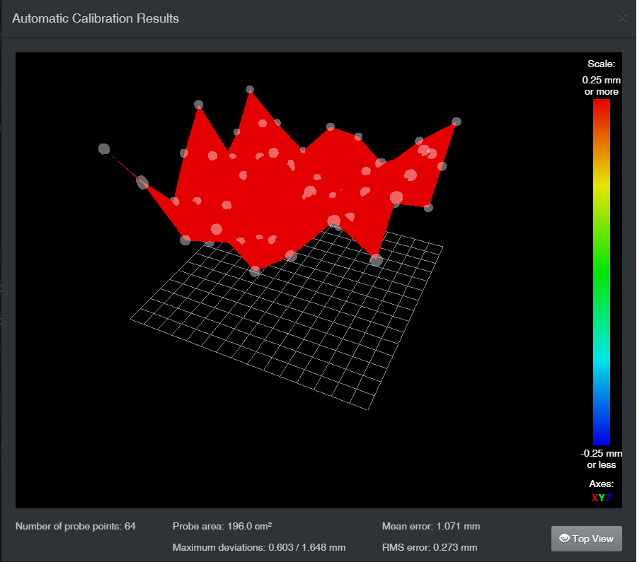
and this is the heatmap I just got: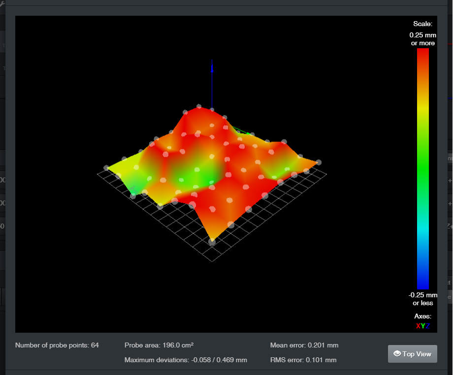
We are using the normal black buildtack and there is no writings or text or white lines. The only variation are the markings left by the older prints. Anyway the surface is like two weeks old.
We do run G29 after homing z and, before every print, we set the z datum then home, and then print (with G29 S1).
The heatmap does load for sure because i can feel the Z stepper moving througout the entire printing process.
It seems like it misreads the heatmap and lower when it shouldent and rises again when it is not supposed to.
What is the correct point to measure the x and y offset from the nozzle? Is there a marking on the IR board I should reference for measuring it?I will also post the config.g below
config (1).gWe are also very confused about the z datum, what is it precisely? How do we store it correctly in the firmware? Looks like a simple single z probe an thats it, maybe we are missing something about it.
PS. We did follow the guides step by step for the set up of the IR probe.
Thank you for your time
-
Can you post your homing files as well as the slicer start gcode you're using?
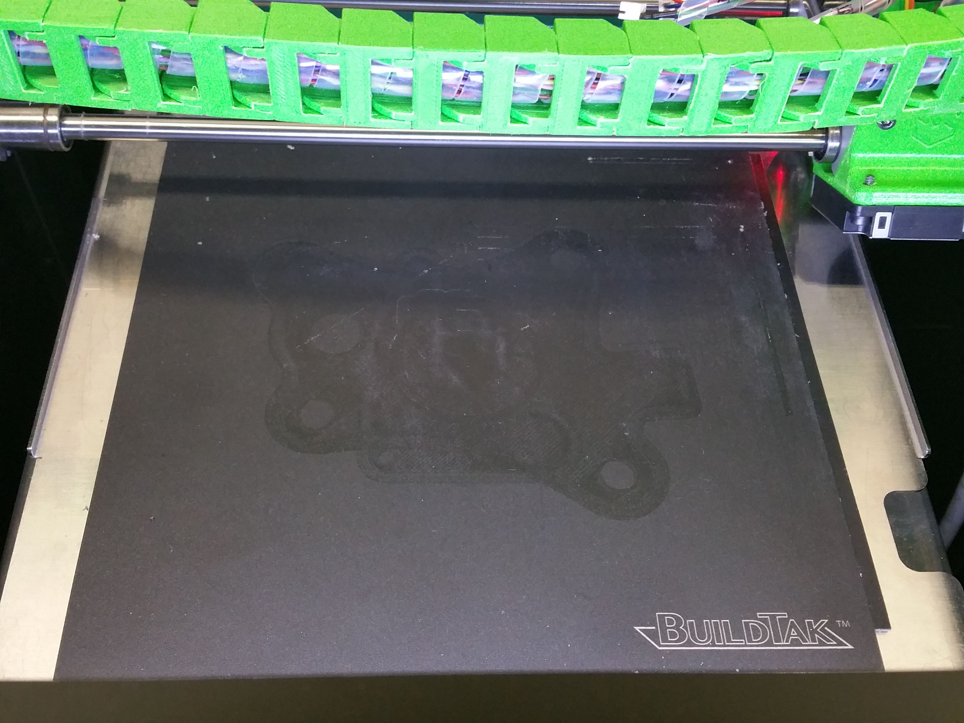
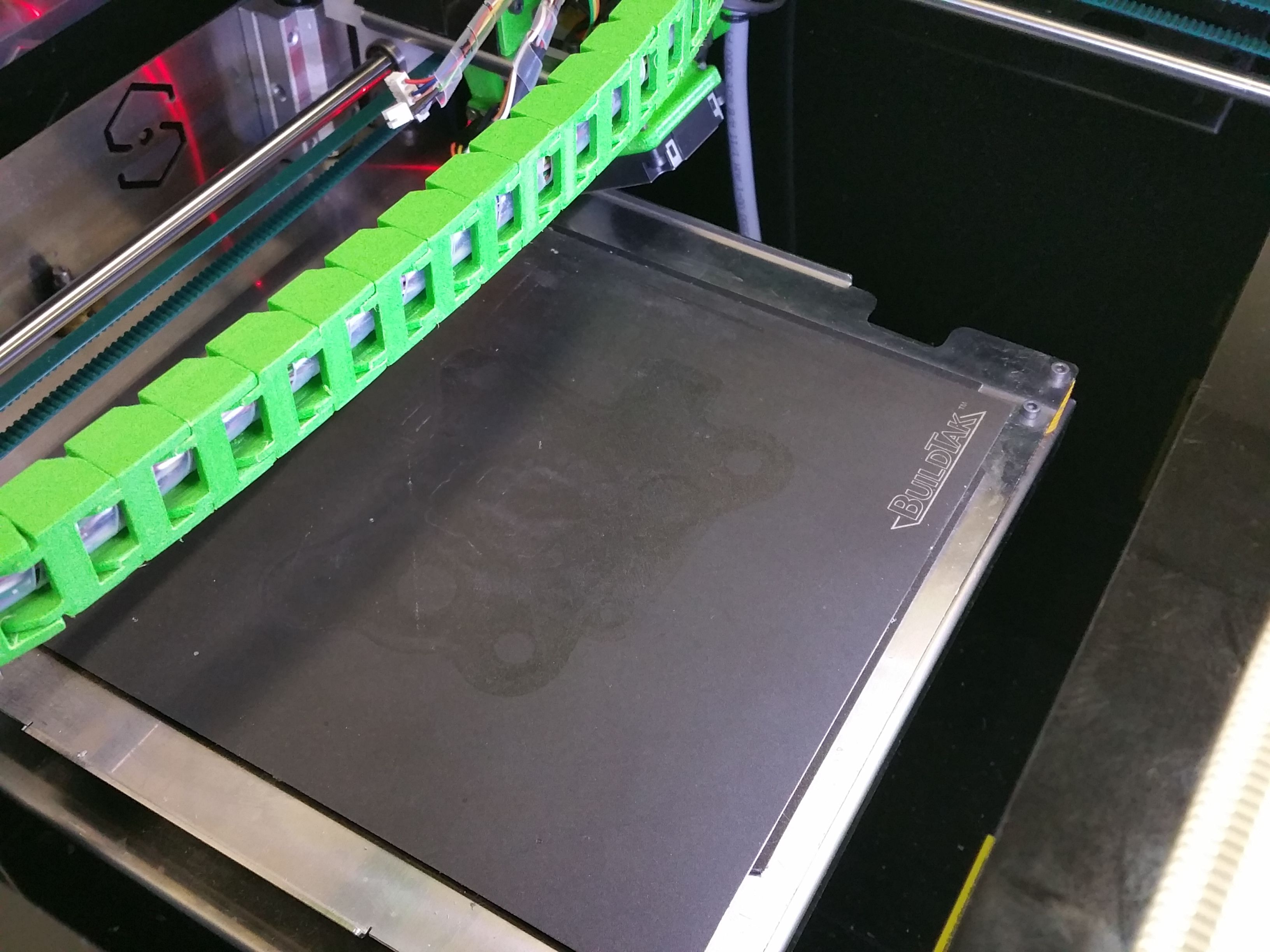
Can you post a photo of the bed itself?
As a test you can use a plain sheet of paper laid on the bed and rerun the G29 to compare the resulting heightmap. The heightmap you posted would seem to indicate that the surface is semi reflective and is giving inconsistent trigger heights across the surface. The test with the white paper should give an idea if this is the case.
The Z datum is simply where Z0 is located. It should be the point where the nozzle touches the bed. All you have to do to define it is probe the center of the bed with G30, which should be in your homeall anyway.
-
; Endstops M574 X1 Y1 Z1 S0 ; set active high endstops ;M574 Z1 S0 ; set endstops controlled by motor stall detection ; Z-Probe ;M574 Z1 S2 ; set endstops controlled by probe M558 P1 H5 F120 T6000 ; disable Z probe but set dive height, probe speed and travel speed G31 P500 X20.3 Y-1.45 Z2.76 ; set Z probe trigger value, offset and trigger height M557 X50:200 Y10:160 S20 ; define mesh grid Are you using an endstop to home the Z axis or are you using the probe?
This is where having homeall would help.
And just as an aside:
M350 Z64 I0 ; configure microstepping without interpolation M350 X64 Y64 Z64 E64:64 I0 ; configure microstepping with no interpolation It's recommended to use x16 microstepping with interpolation unless required for a specific reason. Using higher microstepping can overwhelm the CPU and cause missed steps. x16 with interpolation to x256 will give you the best of both worlds. The CPU will be able to handle the step pulses and the motors will be quiet and smooth getting x256 pulses from the drivers.
-
@Phaedrux hey thanks for the reply!
So here is the start Gcode we are using for every prints:G28 ;Home all axis
T1
G1 Z10
G92 E0 ; set position
G1 X140 Y85; set nozzle position at the center
G30 ; zdatum
G29 S1 ; load bed mesh
G28 ;
G1 Z0.4
G1 X51 Y42.5 F4800 ; move to start
G1 X51 Y117.5 E7.0158 F1800 ; print line
G1 X51.675 Y117.5 F4800 ; move to start
G1 X51.675 Y42.5 E7.0158 F1800 ; print line
G1 E-1.5 F2700 ; retract
G4 P1000
M572 D1 S0.15M117 NG printing..
Here you can find the homeall.g file:
homeall.gAnd those are the pictures of the bed installed on the machine:


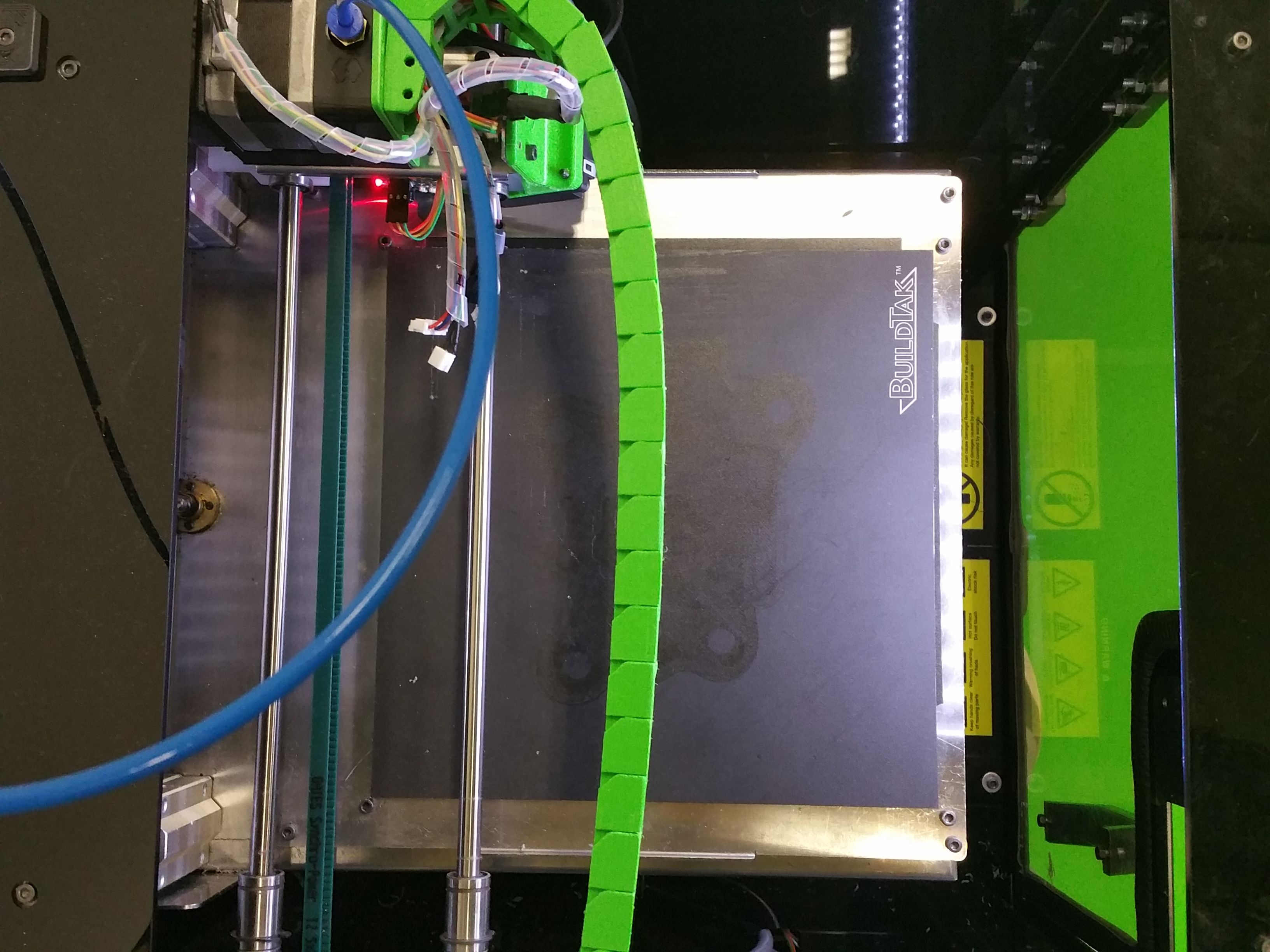
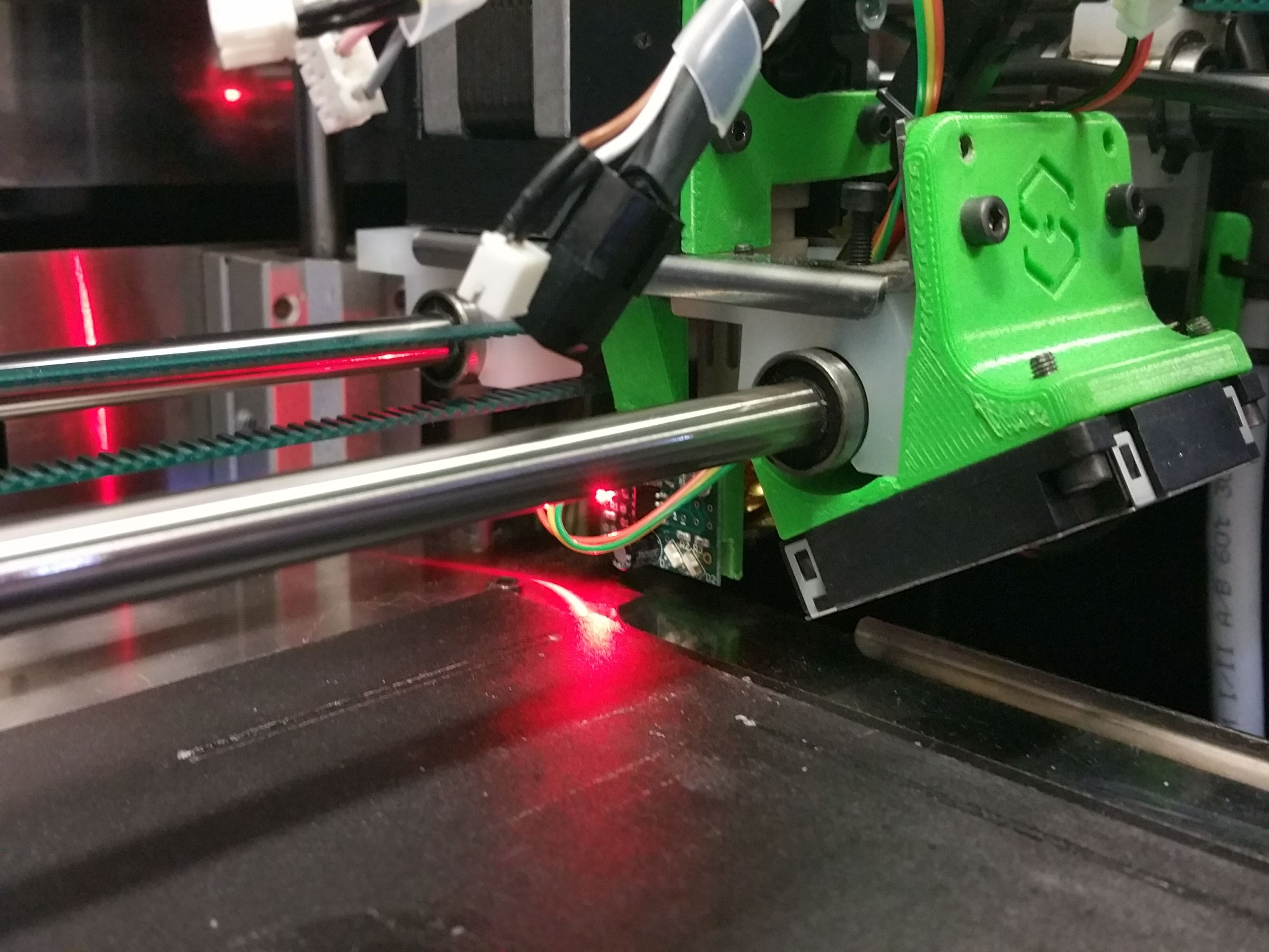
here is a picture of the IR probe mounted:

The bed is illuminated with a common led strip and we are using fluorescent tubes for illuminating the room.
Thanks for the info with the microstepping I'll tweek the values asap.
For the z datum we do include a single probe on the center of the bed during the start gcode but it doesn't stop when the nozzle touches the bed but as soon as the probe triggers which is a few millimiters before the nozzle tip.
Thank you again for your time!
-
Tried a mesh compensation with a piece of paper, disastrous results, here's a picture: