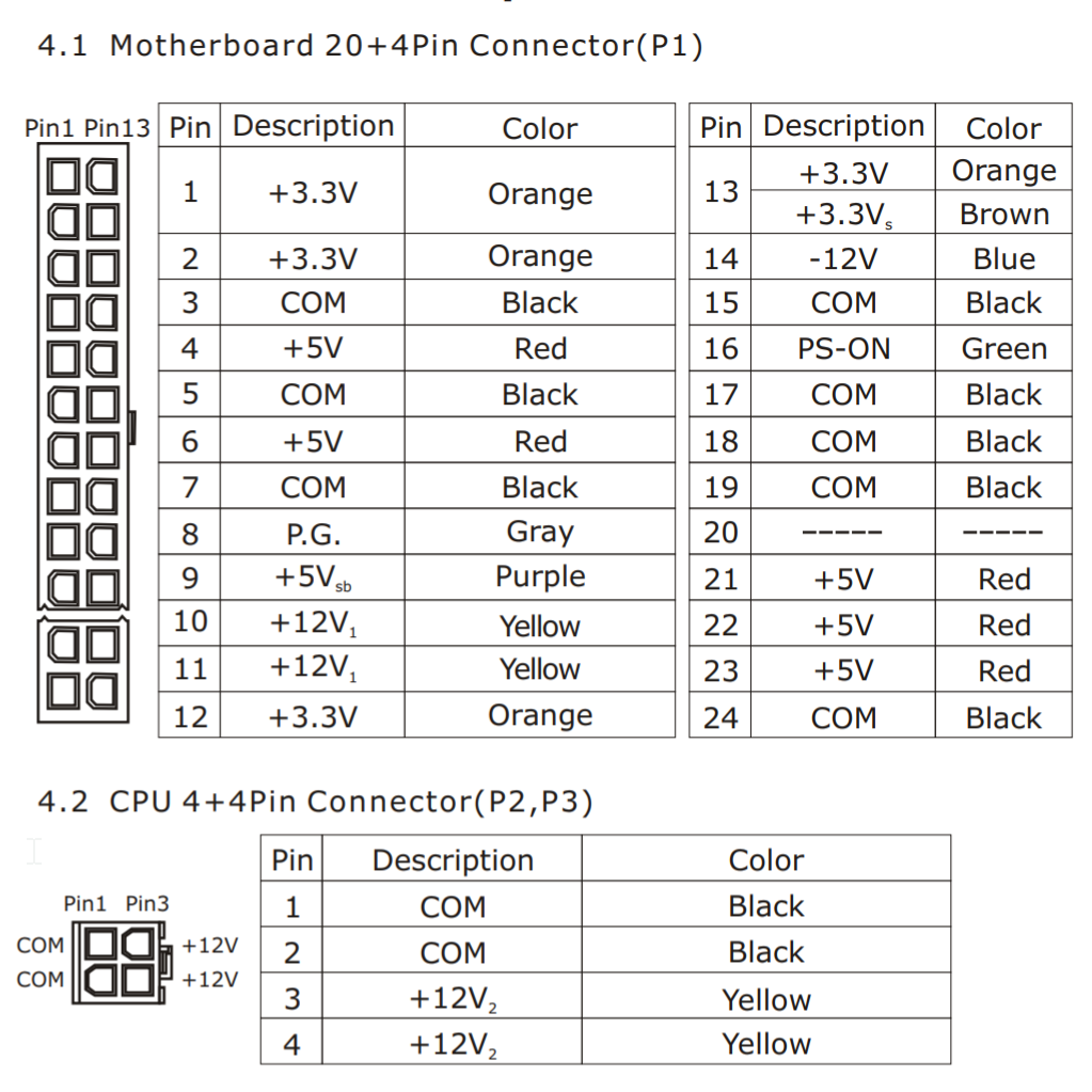
The ATX process from start to finish
-
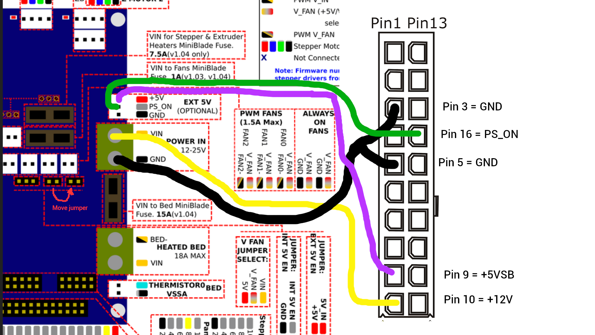
Here's what I intend to do, this way it can server either as a visual guide for others (I'm a very visual person) in case of success, or as a warning of how not to do it if I let the smoke out.

Either extending or re-using wires, depending on lengths... not using the ATX connector, that's just there as a reference.
-
should work, what heated bed would you use?
-
@bearer Nuts, good catch... that's an input, not an output. I probably need another +12V to that, don't I? It's rated 18A on the PSU, so it's likely less than that. So I'll edit my above post...
-
@deltwalrus said in The ATX process from start to finish:
that's an input, not an output.
no its an output, but my point was to find out if you need more yellow wires to carry the current or possibly even find the second 12v rail and wire that to the bed directly to spread the load
-
@bearer Yeah, I just ran down and checked it, you're absolutely correct. The existing supply is 12V, 25A output (rated 300W), and it's sending all 25A to the main VIN. @dc42 advises against sending 18A + 18A in parallel to VIN, but if I wire +12V and GND from the ATX directly to the bed, will I still be able to control the temperature as I can now?
Again, I apologize if these are simplistic or foolish questions, but I'm still learning and am not keen to scorch the place.

-
@deltwalrus said in The ATX process from start to finish:
@dc42 advises against sending 18A + 18A in parallel to VIN
sort of; but sending 18a through at least two wires is different, both the yellow wires on the 24p connector are from the same 12v rail.
then you can take the two yellow wires from the 4p 12v connector and run them to the bed. (also take the two black wires together with the other two).
(of course if your total current draw is less then 18a you'll be fine with just using the two yellow wires from the 24p connectors)
-
@bearer Updated my plan:
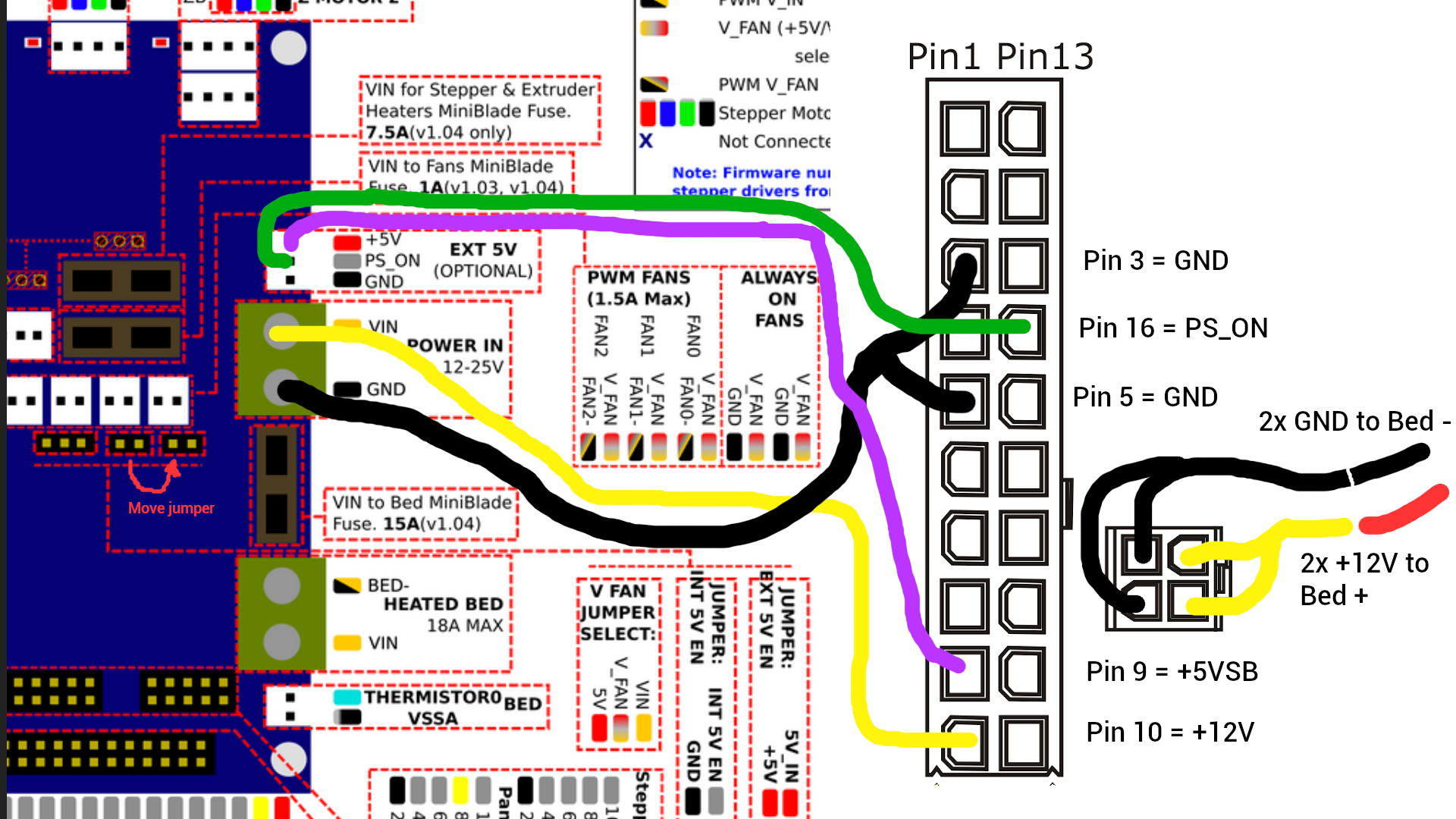
This does still allow temp control via the board, right? I may or may not, possibly, have accidentally wired 12V VIN directly to the board one time by accident, and wondered why the bed just got hotter and hotter whenever I turned the supply on...

And should I also take another +12V from the 24-pin and couple it with pin 10 (so splice together pins 10 and 11)?
-
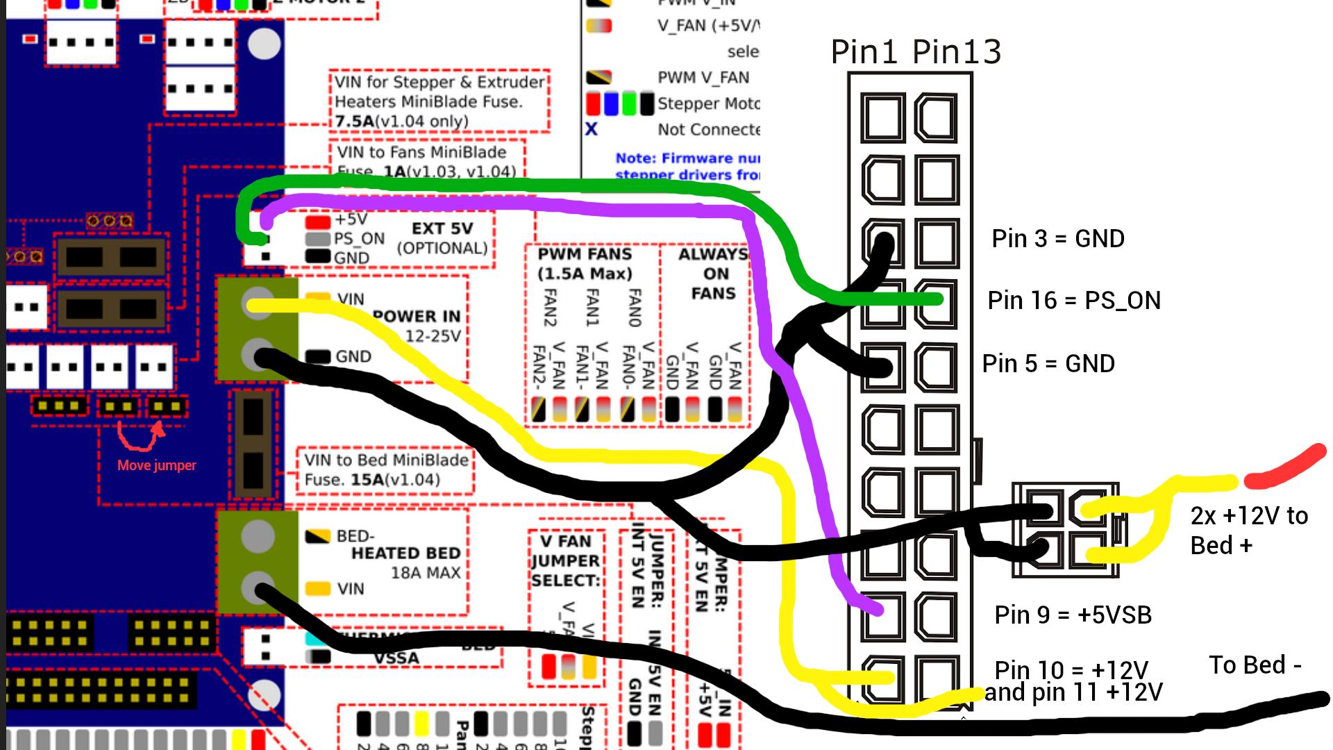
only the yellow/12v straight to the bed.
black/common from the 4p connector to gnd on the duet
and black from the bed to bed- on the duet. -
@deltwalrus said in The ATX process from start to finish:
And should I also take another +12V from the 24-pin and couple it with pin 10 (so splice together pins 10 and 11)?
It wouldn't hurt. It all depends a little on what current your bed will draw, it may be cleaner to use the 6p pci-e conector for everything. (it was 12v1 according to the manual, with only the 4p connector being 12v2)
-
I fear I am confusing this badly, but here's my latest understanding:
-
move the black bed wire up to the from the Vin screw to the bed- screw.
(But again, if your total current is under 18a it may be better to use your initial plan.)
-
Okay, I'm going to try this arrangement out tomorrow:
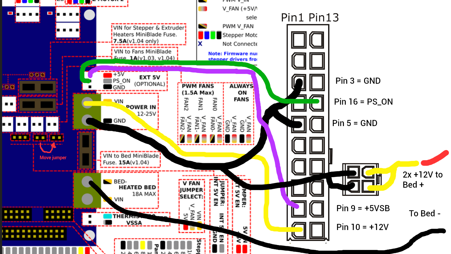
Total current delivered (again, according to the crappy power supply Anycubic provided) was 25A, now it will be 18A + 18A.
Thank you, SO MUCH, for your patience and your expertise. I will report back my results tomorrow on this. Hopefully I don't melt anything...

-
@deltwalrus said in The ATX process from start to finish:
Total current delivered
not quite the same as current used tbh. and you won't actually have 18a+18a. You'll have 360w/12v=30A divided into two 12v rails of 18A max each. so 18A + 12A or 15A + 15A f.ex.
anyways, drawing should be fine, with the caveat the wires are thick enough to carry the current.
-
FYI, I have not yet gotten around to this, as I need to travel for work, but I hope to get it done when I return next weekend. I'm still scared of frying a rather expensive board, so if anyone else has experience doing this, I'm happy to hear any tips you have.