Tool PCB for DB15. Check my work please!
-
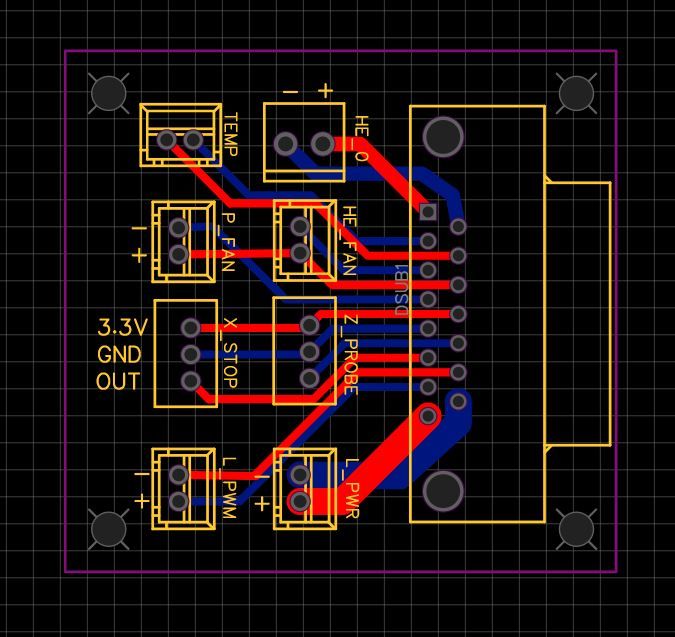
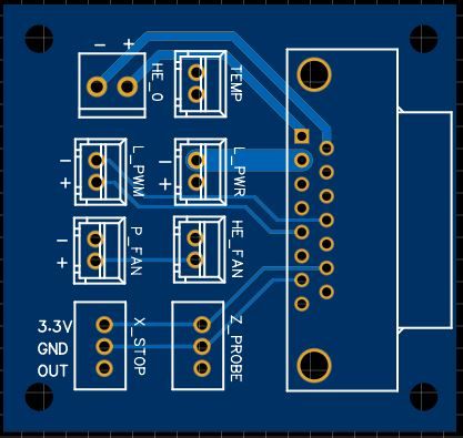
If this is the wrong place for this, forgive me. This is my first attempt at designing a PCB so I wanted to get some feedback before I have it made in case I went full noob on it. Except for the hotend connector (pheonix) they are all XH connectors. L_PWR and L_PWM are for laser control. So how did I do? (I'd share the easyeda link but it says I'm too new to share files yet). Thanks in advance! (One small change since these images is I moved the TEMP plug back from the screw hole a bit so give more space.)
-
I strongly recommend that you put the X stop and Z probe connections at one end of the connector, with the thermistor pins plus any unused pins between those and the heater, fan and LED connections (I am assuming that your LEDs run from +12V or +24V). The reason is that a short between +12V or +24V to +3.3V will wreck a Duet 2 or Duet Maestro. It's easy to get a short between adjacent pins on a D-type connector, if a single strand escapes from a stranded core wire.
-
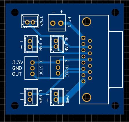
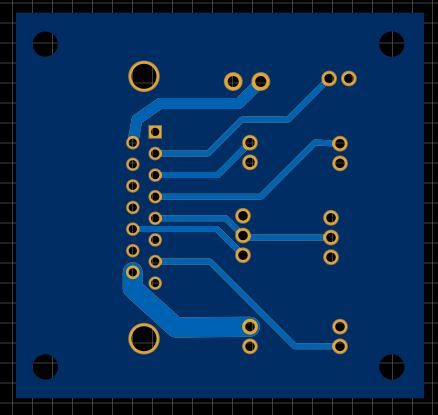
Thanks for the input. Here's a rework. Some of the traces aren't pretty, but I want to keep the thermistor connector next to the hotend heater connector. Some clarification: L_PWR is 12v power for a laser and L_PWM is the PWM signal for said laser.
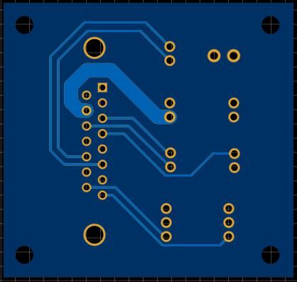
(Edit: slightly tweaked the routing) -
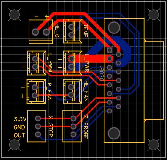
A little puzzled by you having the L_PWR traces twice as thick as the HE_0 traces. If the HE_0 traces are sized for a 40W heater how big is the laser, and is a single pair of d-sub pins sufficient?
Have you taken any derating of the pins and cabling into account; elevated ambient temperature and load on adjacent cores in multi-core cabling can affect the rating.
Also not sure if placing the d-sub on the board as opposed to hanging off the edge is deliberate? If you plan on printing an enclosure its easier to effectively panel mount the connector if you let the connector overhang so you can push it though a cutout in a print/panel without the PCB getting in the way as well as you don't have to take the size of the mating connectors shell into account when making the cutout.
-
Congratulations! Fantastic way to learn EasyEDA and PCB stuff in general.
This is somewhat similar, you may be able to get some ideas:
-
This post is deleted! -
Apologies if this response is all over the place.
@bearer the laser power (L_PWR) traces are for 12v up to 5A vs the heater which is 24v @ <2A.
The DB connector I selected has a 6A/pin rating. I didn't see anything in the data on it about derating. The wires for HE_0 and L_PWR will be a separate (2 pair) run from the others due to the multi-conductor derating from the manufacturer.
For now, the board will be attached to the tool as-is, and I don't have any plans for an enclosure at this time. That said, if I did want to put this in an enclosure, I could see a simple 'U' shaped lid being fine, letting the tool connectors come in the bottom while the DB15 goes out the top.
@Danal That's an interesting design, but there are a few things about it I don't like. First, I'm not a fan of someone that puts "Git Gud" on something they want to sell in this field. I get some people think it's funny, but it seems tacky to me. That aside, my goal is to have everything going to the board on a single connector, rather than the 3 connectors (20pin +2-2pin) like his design.