Y-splitter and Duet 2
-
Good afternoon!!
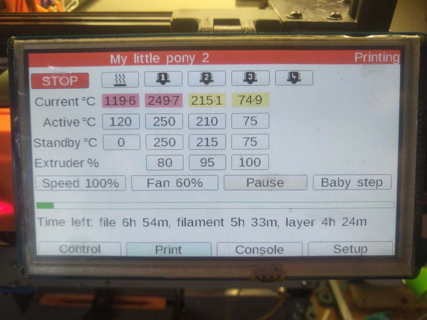
Tell me how to properly configure the printer so that there are no artifacts in the PanelDue.
Problem:
After adding the y-splitter and, accordingly, 2 tools per 1 heater, the tools began to display incorrectly on the panel.
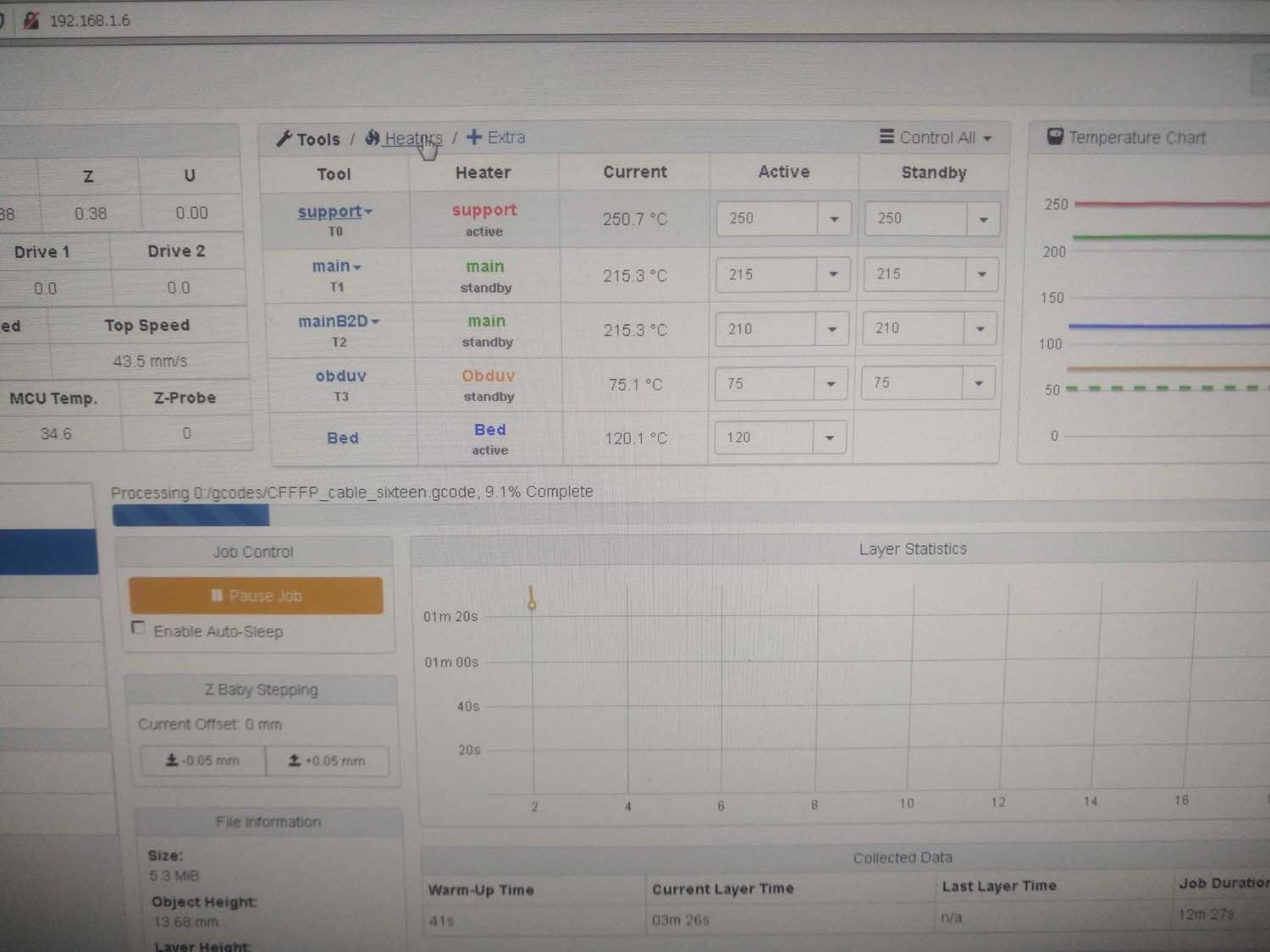
At the same time, the web-interface works correctly.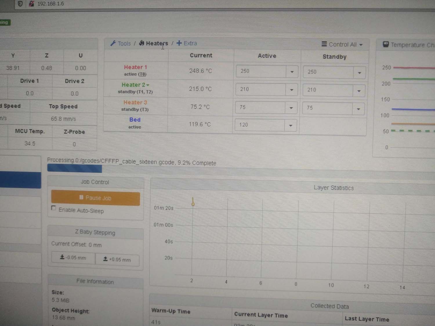
; Configuration file for Duet WiFi (firmware version 1.21)
; executed by the firmware on start-up
;
; generated by RepRapFirmware Configuration Tool v2 on Mon Jan 21 2019 19:24:43 GMT+0300;M929 P"eventlog6.txt" S1
M111 S6; General preferences
G90 ; Send absolute coordinates...
M83 ; ...but relative extruder moves;M584 X0 Y1 Z2 E3:4 ;Driver 0 controls the X motor, 1 controls Y, 2 control Z motors, 3 4 control E motors and 5 control U axis
M584 X0 Y1 Z2 E3:4:6 U5 ;Driver 0 controls the X motor, 1 controls Y, 2 control Z motors, 3 4 6 control E motors and 5 control U axisM667 S1 ; Select CoreXY mode
; Network
M550 P"My little pony 2" ; Set machine name
M551 P"Konica120: ; Set password
M552 S1 ; Enable network
M587 S"TOLO" P"Konica120" ; Configure access point. You can delete this line once connected
M586 P0 S1 ; Enable HTTP
M586 P1 S1 ; Enable FTP
M586 P2 S0 ; Enable Telnet; Drives
M569 P0 S1 ; Drive 0 goes forwards
M569 P1 S1 ; Drive 1 goes forwards
M569 P2 S1 ; Drive 2 goes forwards
M569 P3 S0 ; Drive 3 goes back
M569 P4 S0 ; Drive 4 goes back
M569 P5 S1 ; Drive 5 goes forwards
M569 P6 S1 ; Drive 6 goes forwards;M350 E128:128 I0 ; Configure microstepping without interpolation MK8
;M350 E128:64 I0 ; Configure microstepping without interpolation SUNJIU
M350 E128:64:64 I0 ; Configure microstepping without interpolation SUNJIU+B2DM350 X64 Y64 Z16 I0 ; Configure microstepping with interpolation
M350 U16 I1 ; Configure microstepping with interpolation;M92 X320.00 Y320.00 Z625.00 E1136.00:1136.00 U8.889 ; Set steps per mm MK8
;M92 X320.00 Y320.00 Z625.00 E1136.00:1337.7 U8.889 ; Set steps per mm SUNJIU
;M92 X320.00 Y320.00 Z625.00 E1136.00:1401:883 U8.889 ; Set steps per mm SUNJIU+B2D
;M92 X320.00 Y320.00 Z625.00 E1136.00:1401:1460 U8.889 ; Set steps per mm SUNJIU+B2D(mk8) (lin)
M92 X320.00 Y320.00 Z625.00 E1079.00:1331:1387 U8.889 ; Set steps per mm SUNJIU+B2D(mk8)(good)M566 X600.00 Y450.00 Z120.00 E600.00:600.00:600.00 U200 ; Set maximum instantaneous speed changes (mm/min)
;M566 X600.00 Y450.00 Z120.00 E600.00:900.00 ; Set maximum instantaneous speed changes (mm/min)
M203 X12000.00 Y12000.00 Z360.00 E1600.00:1600.00:1600.00 U7200 ; Set maximum speeds (mm/min)
;M203 X12000.00 Y12000.00 Z360.00 E1600.00:1600.00 ; Set maximum speeds (mm/min)
M201 X3000.00 Y2000.00 Z200.00 E3000.00:2000.00:2000.00 U200 ; Set accelerations (mm/s^2)
;M201 X3000.00 Y2000.00 Z200.00 E3000.00:3000.00 ; Set accelerations (mm/s^2)
M906 X1400.00 Y1400.00 Z1400.00 E1600.00:1700.00:1500.00 U500 I30 ; Set motor currents (mA) and motor idle factor in per cent SUNJIU
;M906 X1400.00 Y1400.00 Z1400.00 E1600.00:1600.00 I30 ; Set motor currents (mA) and motor idle factor in per cent MK8
M84 S300 ; Set idle timeout; Axis Limits
M208 X0 Y0 Z0 U0 S1 ; Set axis min/max
M208 X228 Y245 Z250 U360 S0 ; Set axis maxima; Endstops
M574 X1 Y1 Z1 S1 ; Set active high endstops
M574 U0 S0 ; U has no endstop, but...;Filament sensors
;M591 D0 P2 C3 S1
;M591 D1 P2 C4 S1
M581 E0:1 S1 T1 C1;; Z-Probe
M558 P0 H3 F120 T6000 ; Disable Z probe but set dive height, probe speed and travel speed
M557 X15:210 Y15:230 S100 ; Define mesh grid; Heaters
M305 P0 X0 T100000 B3950 R4700 S"Bed" ; Set thermistor + ADC parameters for heater 0
M301 H0 S0.98 ; Set heater 0 PWM limit to 98%
M143 H0 S140 ; Set temperature limit for heater 0 to 130C
M570 H0 P30 T25 S2 ; Configure heater fault detection
M305 P1 X501 R4700 S"support" ; Configure thermocouple for heater 1
M301 H1 S0.98 ; Set heater 1 PWM limit to 98%
M143 H1 S280 ; Set temperature limit for heater 1 to 280C
M570 H1 P30 T25 S1 ; Configure heater fault detectionM305 P2 X502 R4700 S"main" ; Configure thermocouple for heater 2
M301 H2 S0.98 ; Set heater 2 PWM limit to 98%
M143 H2 S280 ; Set temperature limit for heater 2 to 280C
M570 H2 P30 T25 S1 ; Configure heater fault detectionM305 P3 X3 T100000 B3950 R4700 S"Obduv" ; Set thermistor + ADC parameters for heater 3
M301 H3 S0.98 ; Set heater 3 PWM limit to 98%
M143 H3 S90 ; Set temperature limit for heater 3 to 80C
M570 H3 P30 T25 S1 ; Configure heater fault detectionM305 P102 X4 T100000 B3950 R4700 S"Сold_junction" ; Set thermistor + ADC parameters for heater 4
M305 P103 X5 T100000 B3950 R4700 S"Hot_End" ; Set thermistor + ADC parameters for heater 5
; Fans
M106 P0 S0.3 I0 F500 H-1 C"Obduv" ; Set fan 0 value, PWM signal inversion and frequency. Thermostatic control is turned off
M106 P1 S1 I0 F500 H-1 C"HotEnd" ; Set fan 1 value, PWM signal inversion and frequency. Thermostatic control is turned on
M106 P2 S0.9 I0 F500 H-1 C"Extruders" ; Set fan 2 value, PWM signal inversion and frequency. Thermostatic control is turned off
M106 P3 S0.6 I0 F500 H-1 C"main cool" ; Set fan 2 value, PWM signal inversion and frequency. Thermostatic control is turned off; Tools
M563 P0 S"support" D0 H1 L0 ; Define tool 0
G10 P0 X0 Y0 Z0 ; Set tool 0 axis offsets
G10 P0 R0 S0 ; Set initial tool 0 active and standby temperatures to 0C
M572 D0 S0.2; set extruder 0 pressure advance to 0.4 seconds
╨╢M592 D0 A0.008 B0.0001 L2 ; set parameters for extruder drive 0
M221 S100 D0 ;Set extrude factor override percentageM563 P1 S"main" D1 H2 L1 ; Define tool 1
G10 P1 X-18 Y0 Z0 ; Set tool 1 axis offsets
G10 P1 R0 S0 ; Set initial tool 1 active and standby temperatures to 0C
M572 D1 S0.3 ; set extruder 0 pressure advance to 0.5 seconds
╨╢M592 D1 A0.001 B0.0002 L2; M592 D1 A0.07 B0.0005 L5 ;M592 D1 A0.07 B0.003 L5 ;M592 D1 A0.06 B0.0025 L2 ; set parameters for extruder drive 1
M221 S100 D1 ;Set extrude factor override percentageM563 P2 S"mainB2D" D2 H2 L3 ; Define tool 1
G10 P2 X-18 Y0 Z0 ; Set tool 1 axis offsets
G10 P2 R0 S0 ; Set initial tool 1 active and standby temperatures to 0C
M572 D2 S0.3 ; set extruder 0 pressure advance to 0.5 seconds
╨╢M592 D2 A0.001 B0.0002 L2; set parameters for extruder drive 1
M221 S100 D2 ;Set extrude factor override percentageM563 P3 S"obduv" H3 ; Define tool 2
G10 P3 X0 Y0 Z0 ; Set tool 2 axis offsets
G10 P3 R0 S0 ; Set initial tool 2 active and standby temperatures to 0C;M563 P7 S"Сold junction" H4 ; Define sensor
;M563 P8 S"HotEnd" H5 ; Define sensor
; Automatic saving after power loss is not enabled
; Custom settings are not configured
; Miscellaneous
M501 ; Load saved parameters from non-volatile memory
T0
T1 ; Select first tool
T3
T2 -
Doctor, they ignore me!
-
@Anidal Unfortunately, this is a limitation of the PanelDue firmware. It shows the four tools you have defined at the top, then iterates the heaters below, expecting one heater per tool. Because you are using one heater shared between two tools, it doesn't quite know what to do with this, and ends up showing the active temperature of T1, and standby temperature of T2, on the shared H2 heater.
Unless you really want to set temperatures on the Panel Due, I don't think this will be an issue. It will just display the values. We are currently not planning further PanelDue firmware updates for RepRapFirmware 2, so this will not be fixed with your current setup.
However, with the development and release of RepRapFirmware 3 there is scope to update PanelDue and add a number of requested features and better support a wider variety of setups, once the new Object Model in RRF3 is stable. The PanelDue is on the 'to do' list for this.
Ian
-
Ok. Wait for next version....