Repair servive in Europe/Germany?
-
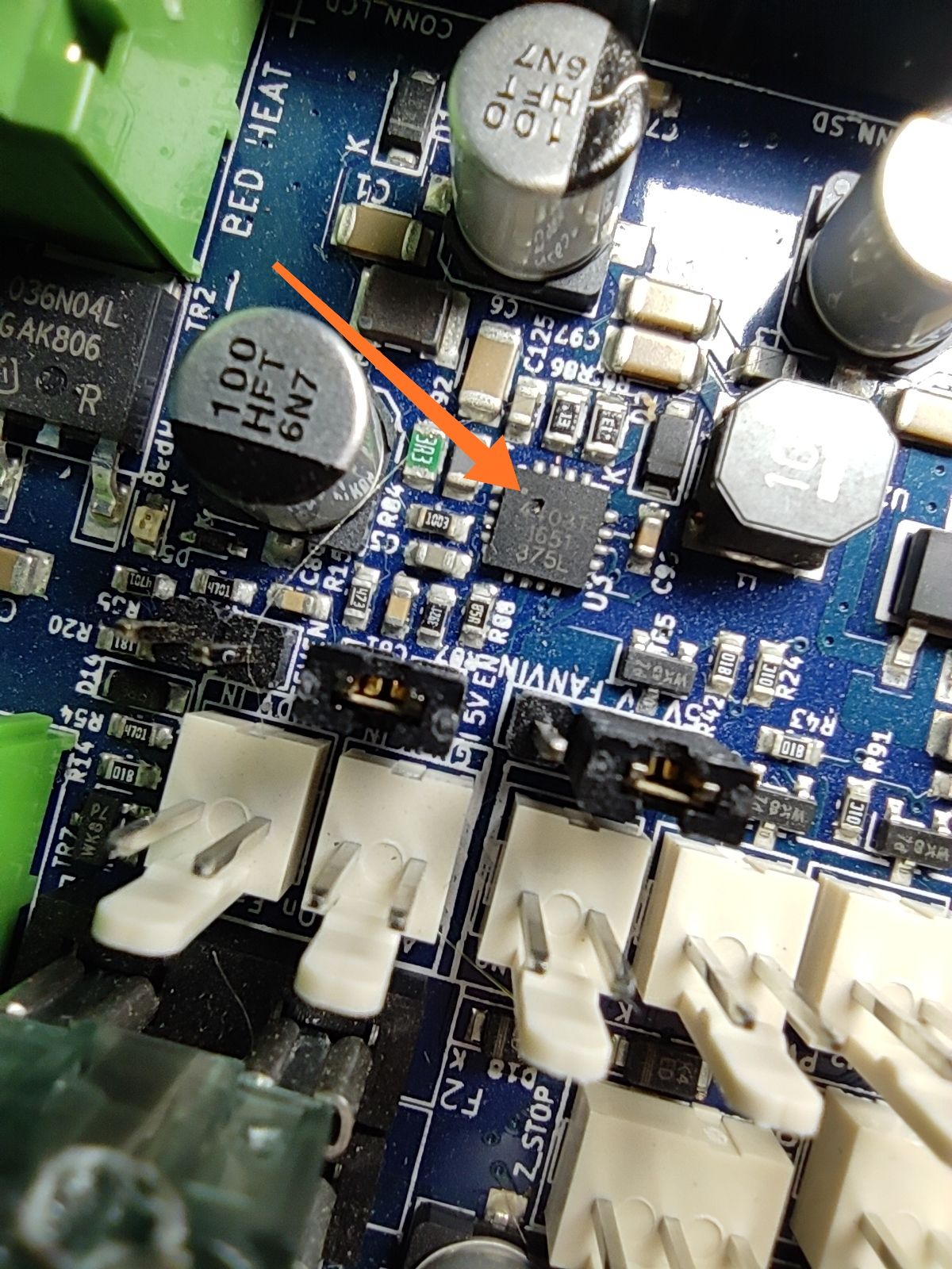
Hi Guys, I destroyed one of my duet 2 WiFi. I shortened ground to something, I found a damaged component on the pcb as you can see on the picture. Is it possible to repair?
Best Regards Cai
-
-
to supplement Ians response;
If the board works with USB power then it may be cheaper (and faster) to stick with a USB supply or even a DC/DC converter connected than to deal with shipping the board off.
You could also ask a well equipped mobile phone repair store if they could do it (but do mention its a 4 layer board with 2oz copper and through hole headers in close proximity).
-
@bearer didn't checked that befor, it works with usb connected, think it's a good sign. So do I have to replace only the marked part? Is it possible to do it on my own. Where can I get this part from?
-
@CaiJonas Possible yes, but I think its fair to say if you have to ask, its probaly not something that you'll succeed with without getting some experience first, and an understanding of what the implications of the circumstance I laid out in the previous post are)
Part is a Allegro A4403GEUTR-T 5v regulator and you can get it from digikey/rs/farnell/arrow pretty much any electronics distributor.
-
@CaiJonas said in Repair servive in Europe/Germany?:
Is it possible to do it on my own
If you have the right tools and knowledge, yes, of course.
First, because it is rather crammed with parts there you want to shield off rest of the parts in vicinity with some kapton tape. Just put kapton tape over all the surounding components and leave square opening so you can access this chip.
Then, preheat a whole board, you can stick it in oven at below 100C (80-90C) or preheat from the bottom using a hair blower or if you have a proper pcb preheat device use that.
Then you want to remove the broken chip, use a low pressure high temp air rework to heat up the chip, when it is heated so it moves lift it with tweezers.
Now add a bunch of flux gel to where chip was and use soldering iron with soldering wick to clean the pads properly.
Clean
Now to put a new one in, this thing don't have pins IIRC so you have to use soldering paste (it is flux gel with suspended micro soldering balls, usually grey color, and much thicker then flux gel itself), put a thin line of soldering paste along the edges of the chip and add more flux gell, put the cip on to the board and heat up chip till it "settles down", press it with tweezers, release, stop heating, let it cool.
This can also be done without soldering paste, with regular solder, by tinning the pcb right amount and just adding a lot of flux, puting chip on top of that soldered pins and again heating the chip till it settles down, this is the way I usually do as I usually can't find where I put the paste

Inspect with usb microscope or loupe if you have bridges and if everything is soldered ok
turn on
Before everything, you might want to test the procedure on some scrap board and maybe check some YT video on how to desolder and solder QFN chip
https://www.youtube.com/results?search_query=solder+qfn -
@arhi said in Repair servive in Europe/Germany?:
Now to put a new one in, this thing don't have pins IIRC so you have to use soldering paste (it is flux gel with suspended micro soldering balls, usually grey color, and much thicker then flux gel itself), put a thin line of soldering paste along the edges of the chip and add more flux gell, put the cip on to the board and heat up chip till it "settles down", press it with tweezers, release, stop heating, let it cool.
I find that I can usually replace a QFN chip once without adding solder. I just add some no-clean flux. It's very hard to add the right amount of solder without a stencil.
Duet WiFi hardware designer and firmware engineer
Please do not ask me for Duet support via PM or email, use the forum
http://www.escher3d.com, https://miscsolutions.wordpress.com -
@dc42 said in Repair servive in Europe/Germany?:
I find that I can usually replace a QFN chip once without adding solder
That was some broad description of the procedure with "go check YT and try on scrap board to get some experience" more then detailed instruction. If you clean the QFN pad on pcb with solder wick and flux as I suggested it will be near to impossible to attach new QFN chip on top of that :). If you leave original solder without cleaning it, it will work.
Basically it depends from QFN to QFN, the Allegro regulators usually have full circumference of the metal available and not that break like some have between bottom and side of the chip. Those are easily soldered with soldering iron
") and looking at the image (will check later on the board too) you used large footprint for the QFN with long pads so even the ugly ones with break between side/bottom should be solderable by soldering iron.
and looking at the image (will check later on the board too) you used large footprint for the QFN with long pads so even the ugly ones with break between side/bottom should be solderable by soldering iron. -
@arhi said in Repair servive in Europe/Germany?:
If you clean the QFN pad on pcb with solder wick and flux as I suggested it will be near to impossible to attach new QFN chip on top of that
Correct. I don't clean the pad with solder wick, I just add a little no-clean flux from a pen.
-
@bearer said in Repair servive in Europe/Germany?:
Allegro A4403GEUTR-T 5v
Hi Guys,
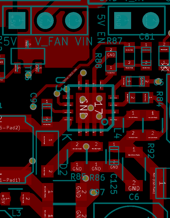
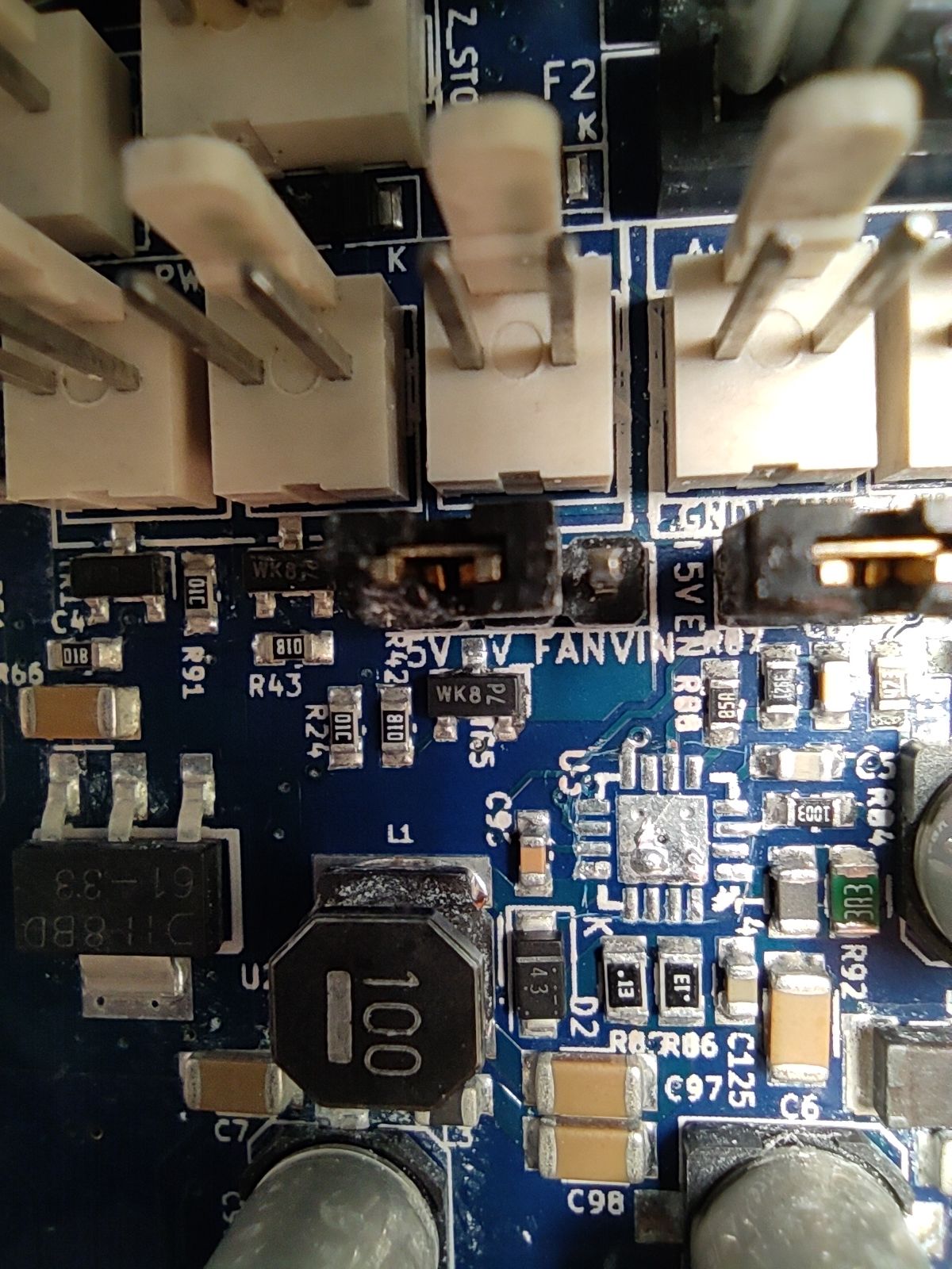
I think I am a step further. I took of the damaged part from the pcb with preheated pcb and some non-celan flux. So far so good. I've ordered now some replacement and I now I am not shure how to orientate the new one. Is that a flatened corner marked on the pcb which should be on the same spot of the replacement?
-
Pin one is oriented to the lower right corner in that picture, yes, and should line up with the dot on the new chip. (oh, and good job!)