• Tags
  • Documentation
  • Order
  • Register
  • Login
Duet3D Logo Duet3D
  • Tags
  • Documentation
  • Order
  • Register
  • Login

Delta Calibration Help

Scheduled Pinned Locked Moved
General Discussion
5
32
1.6k
Loading More Posts
  • Oldest to Newest
  • Newest to Oldest
  • Most Votes
Reply
  • Reply as topic
Log in to reply
This topic has been deleted. Only users with topic management privileges can see it.
  • undefined
    samu_87
    last edited by 1 Apr 2020, 16:04

    Schermata 2020-04-01 alle 18.01.55.png

    I update the firmware to the latest version, and I check all screws and belt...

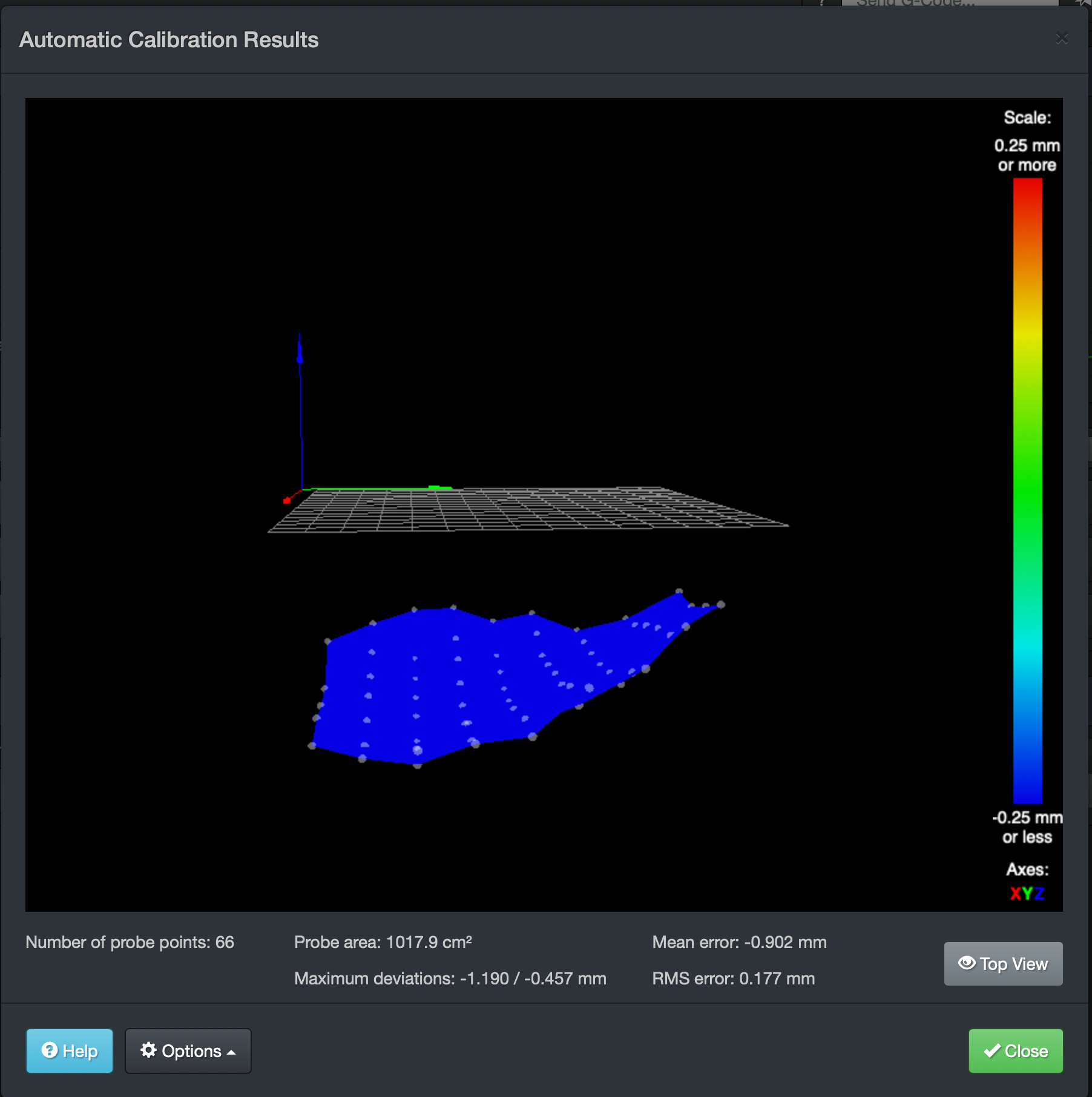
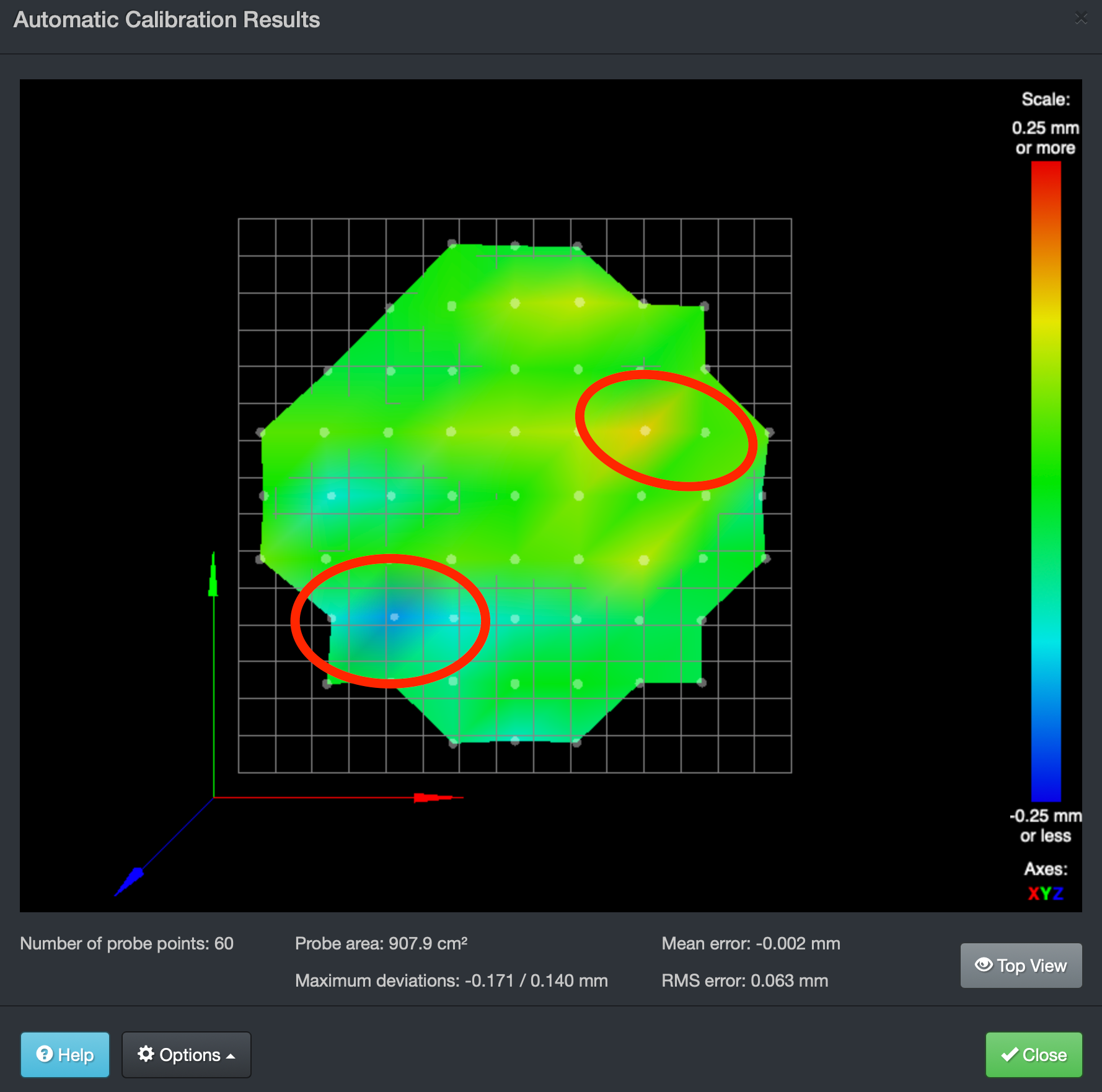
    This is the result without Auto Calibration... I can't see the pattern like in the first pic..

    So it can be the Auto Calibration that give me this issues?

    Anyone have a method to calibrate the printer looking the bed??

    Thanks!

    1 Reply Last reply Reply Quote 0
    • undefined
      Phaedrux Moderator
      last edited by 1 Apr 2020, 19:21

      Have you seen this? https://duet3d.dozuki.com/Wiki/Calibrating_a_delta_printer

      Z-Bot CoreXY Build | Thingiverse Profile

      undefined 1 Reply Last reply 1 Apr 2020, 19:39 Reply Quote 0
      • undefined
        samu_87 @Phaedrux
        last edited by 1 Apr 2020, 19:39

        @Phaedrux Yes thanks! but the strange effect in photo one?

        Thanks!

        1 Reply Last reply Reply Quote 0
        • undefined
          Phaedrux Moderator
          last edited by 1 Apr 2020, 19:46

          The ripples in photo #1 indicate backlash.

          Z-Bot CoreXY Build | Thingiverse Profile

          1 Reply Last reply Reply Quote 0
          • undefined
            samu_87
            last edited by 1 Apr 2020, 20:21

            I measure the back slash and is from about 0.02mm on each axis.

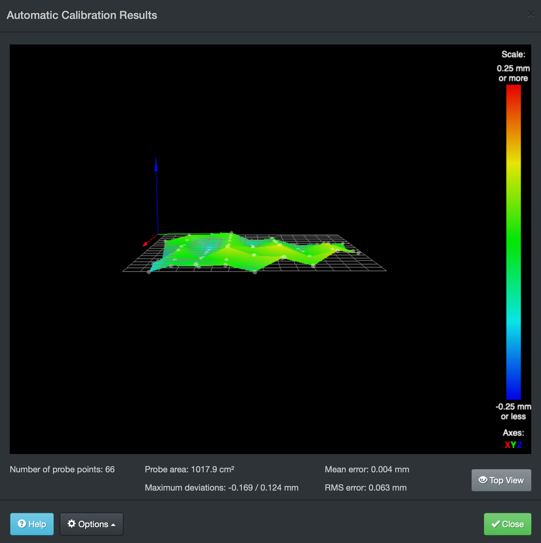
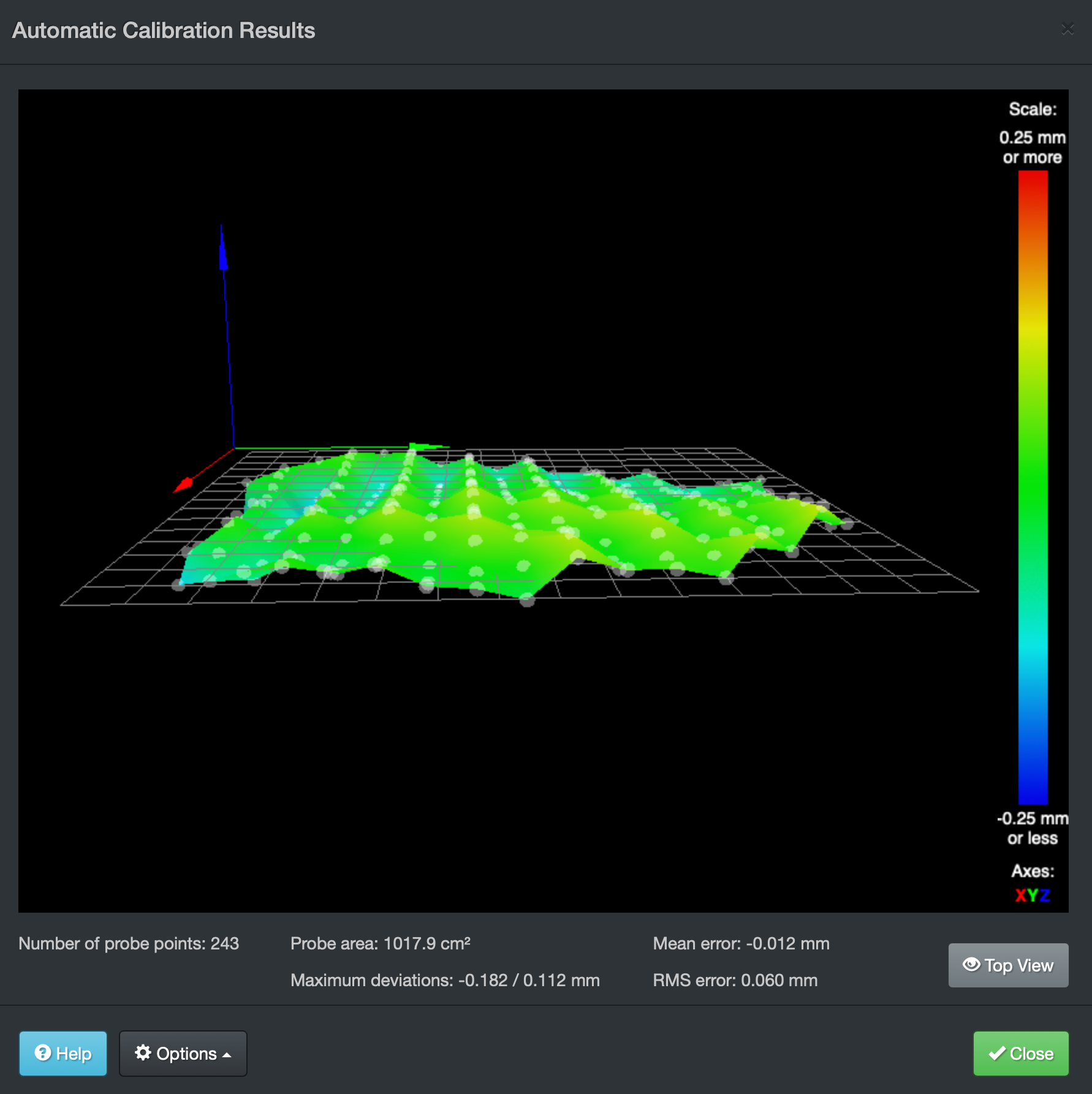
            I made this 2 bed analysis one with double point of each other and the other parameter is equal.
            So I can't say why one line is up from 0 and the other under... The only difference is that in line 0 the effector move from left to right and in line 1 from right to left etc...

            Any idea??

            91467912_639530876900976_3797409589754855424_n.png 91594404_211746480149717_6905838113776467968_n.png

            1 Reply Last reply Reply Quote 0
            • undefined
              Phaedrux Moderator
              last edited by 1 Apr 2020, 23:54

              This is pretty common on deltas that use probes offset to the nozzle. The effector is tilting slightly when moving one direction versus the other which causes the BLTouch to be slightly higher or lower depending on which direction it's going.

              This is why probes like the smart effector or piezo are preferable for delta printers.

              Z-Bot CoreXY Build | Thingiverse Profile

              1 Reply Last reply Reply Quote 1
              • undefined
                clearlynotstef
                last edited by 2 Apr 2020, 02:32

                I'm thinking effector tilt. Because your probe is offset from your nozzle, if your build isn't exactly perfect your effector may tilt slightly at different xy locations, and because the offset probe, this will impact the probe results. Highly recommend probing with the nozzle on deltas.

                1 Reply Last reply Reply Quote 0
                • undefined
                  samu_87
                  last edited by 2 Apr 2020, 08:48

                  Ok Many thanks!! Now is more clear..
                  What can I check to minimize this error? Thanks!

                  undefined 1 Reply Last reply 2 Apr 2020, 20:54 Reply Quote 0
                  • undefined
                    samu_87
                    last edited by 2 Apr 2020, 13:14

                    This post is deleted!
                    1 Reply Last reply Reply Quote 0
                    • undefined
                      Phaedrux Moderator @samu_87
                      last edited by 2 Apr 2020, 20:54

                      @samu_87 said in Delta Calibration Help:

                      Ok Many thanks!! Now is more clear..
                      What can I check to minimize this error? Thanks!

                      I guess that's where it comes down to build quality to limit effector tilt based on position. Normally I think auto calibration can correct for it, but the auto calibration is also affected by the tilt because it uses the probe. Catch 22. The best solution is to change the probe type to one that uses the nozzle. Other than that, go through the build and ensure it's as close to perfection as you can manage.

                      Z-Bot CoreXY Build | Thingiverse Profile

                      1 Reply Last reply Reply Quote 0
                      • undefined
                        samu_87
                        last edited by samu_87 4 May 2020, 13:21 5 Apr 2020, 13:19

                        Maybe is my error, I have this for construction:

                        Schermata 2020-04-05 alle 15.15.10.png

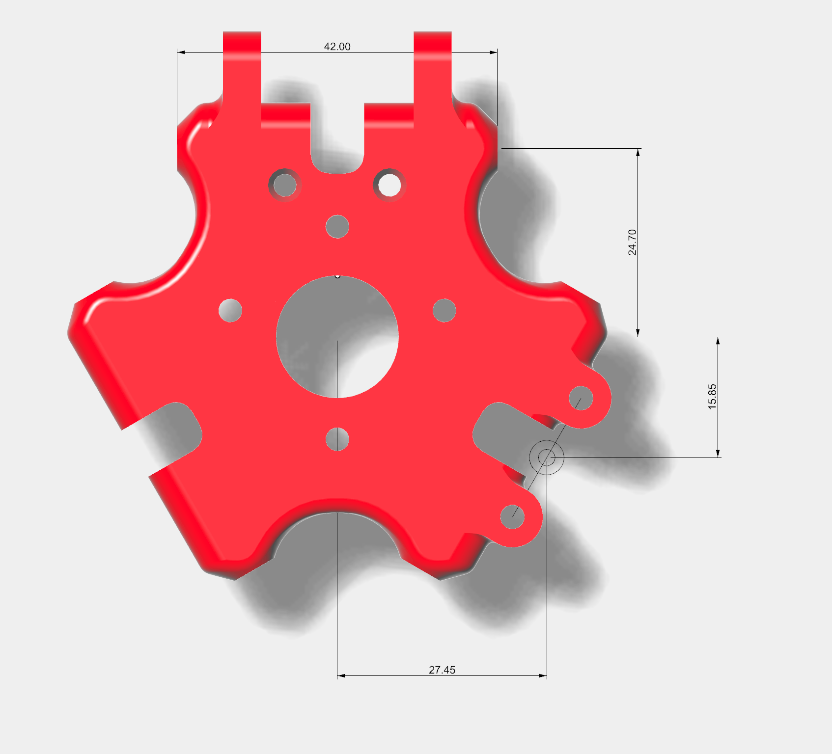
                        So I put the command G31 P500 X27.45 Y-15.85 Z 2.144 for BLTouch..

                        BUT when I go to calculate the point to probe here:
                        http://www.escher3d.com/pages/wizards/wizardbed.php
                        I must put the same probe offset?
                        If I put the same probe offset I think that the probe point are shifted on the left..

                        I thing that this 2 areas are problem to compute the data...

                        Schermata 2020-04-05 alle 15.20.36.png

                        1 Reply Last reply Reply Quote 0
                        • undefined
                          clearlynotstef
                          last edited by 5 Apr 2020, 14:49

                          You can use H offsets in your bed.g for each probe point to account for the tilt when probing.

                          undefined 1 Reply Last reply 5 Apr 2020, 21:10 Reply Quote 0
                          • undefined
                            samu_87 @clearlynotstef
                            last edited by 5 Apr 2020, 21:10

                            @clearlynotstef said in Delta Calibration Help:

                            You can use H offsets in your bed.g for each probe point to account for the tilt when probing.

                            Okay and how can I set the H parameter? How can I measure?

                            1 Reply Last reply Reply Quote 0
                            • undefined
                              Phaedrux Moderator
                              last edited by 5 Apr 2020, 22:36

                              https://duet3d.dozuki.com/Wiki/Gcode#Section_G30_Single_Z_Probe

                              The optional H parameter is a height correction for that probe point. It allows for the Z probe having a trigger height that varies with XY position. The nominal trigger height of the Z probe (e.g. at bed centre) is declared in the Z parameter of the G31 command in the config.g file. When you probe using G30 and the probe triggers, the firmware will assume that the nozzle is at the nominal trigger height plus the value you have in the H parameter.

                              https://duet3d.dozuki.com/Wiki/Calibrating_a_delta_printer#Section_Setting_up_the_bed_g_file

                              Adding trigger height corrections to the bed.g file
                              You may wish to omit this section for first-time calibration and return to it later.

                              Ideally, your Z probe will have exactly the same trigger height at each probe point. In practice it may not:

                              If your Z probe is displaced from the nozzle, small amounts of effector tilt will change the relative heights of the Z probe and the nozzle, which changes the effective trigger height
                              If you are using sensors in the bed mounts, the force required to activate the sensors may vary depending on whether you are probing close to one of them
                              We recommend that you measure the trigger height at several of your probe points. If you determine that the trigger height is the same at all positions, that's excellent. If it isn't, then for accurate calibration results you should measure the trigger height at every probe point and add trigger height corrections to bed.g.

                              To measure the trigger height see "measuring the trigger height section above", repeat for the other XY positions you want to check

                              Use the trigger height at the centre of the bed as the reference, and put that value in the Z parameter of your G31 command in config.g. For each of the G31 commands in bed.g except for the one at that centre point, add parameter Hxxx where xxx = (trigger height at that point) - (trigger height at centre point).

                              Z-Bot CoreXY Build | Thingiverse Profile

                              undefined 1 Reply Last reply 8 Apr 2020, 11:13 Reply Quote 0
                              • undefined
                                samu_87 @Phaedrux
                                last edited by 8 Apr 2020, 11:13

                                @Phaedrux Yes but if I measure this with BLTouch and update H values in Bed.g when I run the AutoCalibration for Delta printer I fond that the algorithm do nothin...?

                                Thats right?

                                undefined 1 Reply Last reply 8 Apr 2020, 20:39 Reply Quote 0
                                • undefined
                                  Phaedrux Moderator @samu_87
                                  last edited by 8 Apr 2020, 20:39

                                  @samu_87 said in Delta Calibration Help:

                                  @Phaedrux Yes but if I measure this with BLTouch and update H values in Bed.g when I run the AutoCalibration for Delta printer I fond that the algorithm do nothin...?

                                  Thats right?

                                  Sorry but I'm not a delta user so my understanding of how it's supposed to go is pretty limited.

                                  Can you post an example of what you changed?

                                  Z-Bot CoreXY Build | Thingiverse Profile

                                  1 Reply Last reply Reply Quote 0
                                  • undefined
                                    samu_87
                                    last edited by 9 Apr 2020, 00:41

                                    Delta Auto Calibration is the function to calibrate the delta parameters M665 and M666 I do not read the full algorithm but I think that all the calculation is base from the different hight of the probing points, so if I set the H parameter the algorithm can't work I think..

                                    Maybe @dc42 can help...

                                    1 Reply Last reply Reply Quote 0
                                    • undefined
                                      Danal
                                      last edited by Danal 4 Sept 2020, 01:47 9 Apr 2020, 01:45

                                      Calibration is G32 and the contents of bed.g Depending on the parameter in the last G30 in bed.g, it will update M665 and M666, exactly which parameters depends on the G30 settings. Mesh is G29 and is based on a grid and produces the pictures above. Which one are we really talking about?

                                      It is true that Mesh depends on calibration being correct. It is also true that the mesh picture can look odd because both are being thrown off by a tilted effector and an offset probe.

                                      That's why the instructions here: https://duet3d.dozuki.com/Wiki/Calibrating_a_delta_printer#Section_Setting_up_the_bed_g_file

                                      Describe how to measure the error and each separate probe point used by G32 and bed.g. After you measure them, you put the numbers, either positive or negative, in the H parameters of each separate probe point in bed.g. And then you probe and mesh again, and the picture will look a lot better (and prints will work better, if you print with mesh on).

                                      Having said all of that, just my personal opinion, I wouldn't do that. I'd fix the tilted effector, or change to a smart effector (where the nozzle is the probe).

                                      Delta / Kossel printer fanatic

                                      undefined 1 Reply Last reply 9 Apr 2020, 09:47 Reply Quote 0
                                      • undefined
                                        samu_87 @Danal
                                        last edited by 9 Apr 2020, 09:47

                                        @Danal If I put the H values I have this:

                                        Schermata 2020-03-31 alle 21.58.34.png

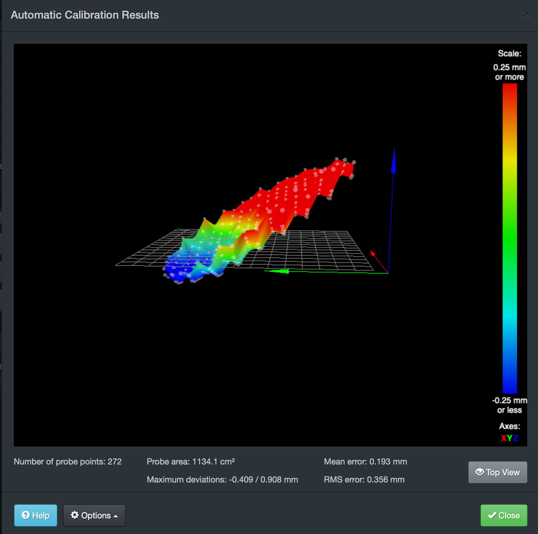
                                        Because I think that the G32 can't calculate properly delta geometry correction...

                                        How can I fix tilting in effector?

                                        1 Reply Last reply Reply Quote 0
                                        • undefined
                                          samu_87
                                          last edited by 9 Apr 2020, 12:28

                                          I made this Macro GCode to make easy to set the H parameter it can be fine?

                                          M140 S27 ;Constant Bed Temperature
                                          G1 X0 Y0 Z15 ;Make X0Y0 the ZERO of the bed
                                          G30 S-1 ;Copy in Bed.g the results, H parameter
                                          G92 Z0
                                          G1 X0.00 Y170.00 Z15
                                          G30 S-1
                                          G1 X104.21 Y124.20 Z15
                                          G30 S-1
                                          G1 X145.69 Y25.69 Z15
                                          G30 S-1
                                          G1 X124.09 Y-71.64 Z15
                                          G30 S-1
                                          G1 X50.60 Y-139.02 Z15
                                          G30 S-1
                                          G1 X-55.45 Y-152.35 Z15
                                          G30 S-1
                                          G1 X-147.22 Y-85.00 Z15
                                          G30 S-1
                                          G1 X-167.42 Y29.52 Z15
                                          G30 S-1
                                          G1 X-109.27 Y130.23 Z15
                                          G30 S-1
                                          G1 X0.00 Y85.00 Z15
                                          G30 S-1
                                          G1 X59.87 Y34.56 Z15
                                          G30 S-1
                                          G1 X53.62 Y-30.96 Z15
                                          G30 S-1
                                          G1 X0.00 Y-69.13 Z15
                                          G30 S-1
                                          G1 X-73.61 Y-42.50 Z15
                                          G30 S-1
                                          G1 X-73.61 Y42.50 Z15
                                          G30 S-1
                                          1 Reply Last reply Reply Quote 0
                                          22 out of 32
                                          • First post
                                            22/32
                                            Last post
                                          Unless otherwise noted, all forum content is licensed under CC-BY-SA