Sanity check of wiring, and fly back diode question
-
Hi all, this is my first post so an introduction! I’m relatively new to 3d printing, I’m mechanically biased with a what I thought a was a reasonable amount of electrical knowledge, then I started wiring my shiney new board, and realised I’ve jumped in the deep end.
So I have the Duet 3 board (v1) and an Ender 5 pro with all stock components (24v Landy PSU) with addition of a Bltouch v3.1, and an rpi3b+ Powered by the duet, which is now configured,updated (sudo update/upgrade) and connected to the internet.
I’ve re-crimped and attached all connections could someone take a look at the picture and see if I’ve made any obvious mistakes I don’t fancy burning anything out! Please forgive the colour codes for the power in they will be changed!
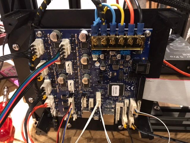
The other question I have and this really is showing my lack of knowledge, I have the nozzle heater connected to the 2 pin VH socket OUT_1 does this require a flyback diode?
Thanks in advance
-
Second question: answer is "no"
-
Thank you for your swift reply, hopefully ill be able to start configuring the printer shortly then!
many thanks
")
-
Yeah diodes are only needed for inductive loads, and the common heater cartridges are purely resistive; so no need for the diode. (outputs 0-3 does not have any, but outputs 4-8 do if you find youself in need).
Nothing immediately obvious with the wiring, bit also not easy to say whats going on due to the distance and low resolution.
Best advice before turning on the power is to take a multimeter and measure continuity from ground and to 3.3v, 5v and 12v pins to rule out any short circuits before flipping the switch.
-
Thanks I will go through it all again just to be sure, I have already moved the x and y end stops to io4 and 5 instead of io0 and 1 as I believe io0 is used for the paneldue...
Added the same picture again but higher resolution I’ll try get some pictures as soon as I can.

Thanks again
-
I suggest you double check the + and - polarity of the power feed from the PSU to the VIN connections of the Duet.
We normally recommend that you run separate wires from the PSU to the Duet 3 for the bed heafer VIN and main VIN terminals, although it only really matters if the total power consumption is likely to exceed 15-20A.
Duet WiFi hardware designer and firmware engineer
Please do not ask me for Duet support via PM or email, use the forum
http://www.escher3d.com, https://miscsolutions.wordpress.com -
Thank you i shall recheck everything first thing in the morning, I know there are spare 24v terminals on the PSU so I will run new cables as you suggest, I really appreciate everybody’s feedback, you have saved me a lot of head scratching!
-
I have re-checked the VIN connections as suggested and also repositioned the board and added separate wires from the PSU to the bed heater VIN, I have also ordered new larger diameter wires to be on the safe side and future proof myself!
I have re-checked all wiring for shorts and continuity and instead of posting a dozen bad pictures I've listed the connections I've made instead -
VIN +/- = 24v PSU terminals
Bed heater VIN +/- = 24v PSU terminals
Out0 = to bed heater insuring the polarity is reversed as per the boardDriver wiring as per original (outer wires direct with inner wires swapped over at the stepper motor plug, all re-crimped/soldered with extra insulation.
Driver 0 = X stepper motor
Driver 1 = Y stepper motor
Driver 2 = Z stepper motor
Driver 3 = Extruder motorOut 1 = Nozzle heater wiring same order as the it was removed from original board
Out 4 =- GND - Hot end fan NEG wire
V_outlc1 - Hot end fan POS wire
Out 5 = same as Out 4 but for part cooling fan
Temp_0 = Hot end thermistor wiring same order as the it was removed from original board
Temp_1 = Bed thermistor matching Temp_0IO_4 = X axis end stop
- GND - Signal
IO4.in - Voltage
IO_5 = Y axis end stop matching IO_4
IO_7 = BLTouch V3.1
- IO7.in - white wire
GND - Black+Blue wire
IO7.out - Yellow wire
5v_ext = Red wire
SBC connector - RPI3B+ ribbon cable oriented the correct way.
Sorry for the long post I have gone through as many of the guides and posts as possible, I just want to do everything right and not miss anything!
Thanks again for your input
- GND - Hot end fan NEG wire