Duex5 Not working Properly - Warranty Claim
-
Hello I purchased a Duet 2 / Duex5 through a US vendor Filastruder in a Railcore2 kit.
Per your warranty instructions I am opening up a forum thread.
This is still in the build process and it started throwing errors and shortly after configuration and testing.
Issue #1.. I get Warning: high temperature reported by driver(s) 1 2 from a cold start and just homing X (I even dropped the stepper voltages.)
Issue #2 the Z-steppers stopped working (even tested by swapping to other working stepper motors.)Similar to forum thread https://forum.duet3d.com/topic/9460/duex5-not-workingM115
FIRMWARE_NAME: RepRapFirmware for Duet 2 WiFi/Ethernet FIRMWARE_VERSION: 2.05.1 ELECTRONICS: Duet WiFi 1.02 or later FIRMWARE_DATE: 2020-02-09b1Firmware Name: RepRapFirmware for Duet 2 WiFi/Ethernet
Firmware Electronics: Duet WiFi 1.02 or later
Firmware Version: 2.05.1 (2020-02-09b1)
WiFi Server Version: 1.23
Web Interface Version: 1.22.6M122
=== Diagnostics ===
RepRapFirmware for Duet 2 WiFi/Ethernet version 2.05.1 running on Duet WiFi 1.02 or later
Board ID: 08DJM-9178L-L4MSJ-6J1FJ-3S86J-KB2LN
Used output buffers: 3 of 24 (12 max)
=== RTOS ===
Static ram: 25712
Dynamic ram: 93140 of which 416 recycled
Exception stack ram used: 544
Never used ram: 11260
Tasks: NETWORK(ready,744) HEAT(blocked,1232) MAIN(running,3760) IDLE(ready,160)
Owned mutexes:
=== Platform ===
Last reset 00:05:39 ago, cause: power up
Last software reset at 2020-04-11 15:30, reason: User, spinning module GCodes, available RAM 11064 bytes (slot 1)
Software reset code 0x0003 HFSR 0x00000000 CFSR 0x00000000 ICSR 0x0441f000 BFAR 0xe000ed38 SP 0xffffffff Task 0x4e49414d
Error status: 0
Free file entries: 10
SD card 0 detected, interface speed: 20.0MBytes/sec
SD card longest block write time: 0.0ms, max retries 0
MCU temperature: min 24.6, current 32.3, max 32.4
Supply voltage: min 23.9, current 24.1, max 24.2, under voltage events: 0, over voltage events: 0, power good: yes
Driver 0: ok, SG min/max 640/640
Driver 1: ok, SG min/max 640/640
Driver 2: ok, SG min/max not available
Driver 3: ok, SG min/max not available
Driver 4: ok, SG min/max not available
Date/time: 2020-04-11 18:11:51
Cache data hit count 1017728302
Slowest loop: 4.59ms; fastest: 0.06ms
I2C nak errors 0, send timeouts 0, receive timeouts 0, finishTimeouts 0, resets 0
=== Move ===
Hiccups: 0, FreeDm: 160, MinFreeDm: 156, MaxWait: 43002ms
Bed compensation in use: none, comp offset 0.000
=== DDARing ===
Scheduled moves: 10, completed moves: 10, StepErrors: 0, LaErrors: 0, Underruns: 0, 0
=== Heat ===
Bed heaters = 0 -1 -1 -1, chamberHeaters = -1 -1
Heater 1 is on, I-accum = 0.0
=== GCodes ===
Segments left: 0
Stack records: 1 allocated, 0 in use
Movement lock held by null
http is idle in state(s) 0
telnet is idle in state(s) 0
file is idle in state(s) 0
serial is idle in state(s) 0
aux is idle in state(s) 0
daemon is idle in state(s) 0
queue is idle in state(s) 0
autopause is idle in state(s) 0
Code queue is empty.
=== Network ===
Slowest loop: 39.79ms; fastest: 0.00ms
Responder states: HTTP(0) HTTP(0) HTTP(0) HTTP(0) FTP(0) Telnet(0) Telnet(0)
HTTP sessions: 1 of 8- WiFi -
Network state is running
WiFi module is connected to access point
Failed messages: pending 0, notready 0, noresp 0
WiFi firmware version 1.23
WiFi MAC address bc:dd:c2:31:93:a5
WiFi Vcc 3.35, reset reason Turned on by main processor
WiFi flash size 4194304, free heap 22736
WiFi IP address 192.168.200.34
WiFi signal strength -51dBm, reconnections 0, sleep mode modem
Socket states: 0 0 0 0 0 0 0 0
**=======================================
Tested each pin on ribbon cable --- OKPlease let me know if there is any additional information or diagnostics you need performed.
Tom - WiFi -
-
Additional Information:
-
The BLTouch is plugged into the Duex5 and works fine, only issue #1 and #2 exist.
-
I removed the ribbon cable and homed X and Y numerous times. I did NOT receive any stepper overheat warnings.
-
-
-- checked continuity of fuse -- OK
-- Checked back of board for bad solder joints -- appear to be none
-- no wire strands on board that could cause shorts. -
Can you provide a detailed close up photo of the driver chips?
-
@BladerunnerxRC Was the M122 done with the Duex connected? If so, it's not being recognised. Check ribbon cable connection, and that no pins have been bent over underneath the ribbon cable connector on both Duet and Duex.
Please post your config.g, and also take a photo of the Duet and Duex connected, showing jumpers set on the Duex, and the power wiring (you should have run a very short and thick ground wire directly from the negative (-) terminal of the VIN terminal block on the Duex board to the negative VIN terminal of the Duet).
Ian
Bed-slinger - Mini5+ WiFi/1LC | RRP Fisher v1 - D2 WiFi | Polargraph - D2 WiFi | TronXY X5S - 6HC/Roto | CNC router - 6HC | Tractus3D T1250 - D2 Eth
-
@droftarts HI,
-- checked male pins in ribbon socket --- OK
-- checked continuity of each wire in the ribbon cable


======
config.g; Configuration file for My Printer
; Communication and general
M111 S0 ; Debug off
M550 PRailCore2 ; Machine name and Netbios name (can be anything you like)
M551 Pmyrap ; Machine password (used for FTP)
;*** If you have more than one Duet on your network, they must all have different MAC addresses, so change the last digits
;M540 P0xBE:0xEF:0xDE:0xAD:0xFE:0xEE ; MAC Address
;*** Wifi Networking
M552 S1 ; Enable WiFi
M586 P0 S1 ; enable HTTP
M586 P1 S1 ; enable FTP
M555 P2 ; Set output to look like Marlin
M575 P1 B57600 S1 ; Comms parameters for PanelDueG21 ; Work in millimetres
G90 ; Send absolute coordinates...
M83 ; ...but relative extruder moves; Axis and motor configuration
M669 K1 ; CoreXY modeM584 X0 Y1 Z5:6:7 E3:4:8:9 ; Map Z to drivers 5, 6, 7. Define unused drivers 3,4,8 and 9 as extruders
M569 P0 S0 ; Drive 0 goes forwards (change to S0 to reverse it) X stepper (Rear)
M569 P1 S1 ; Drive 1 goes backwards Y Stepper (Front)
M569 P2 S1 ; Drive 2 goes forwards Unused
M569 P3 S0 ; Drive 3 goes forwards Extruder
M569 P4 S1 ; Drive 4 goes forwards Extruder (unused)
M569 P5 S0 ; Drive 5 goes backwards Front Left Z
M569 P6 S0 ; Drive 6 goes backwards Rear Left Z
M569 P7 S0 ; Drive 7 goes backwards Right Z;Leadscrew locations
M671 X-10:-10:333 Y22.5:277.5:150 S7.5 ;Front left, Rear Left, Right S7.5 is the max correction - measure your own offsets, to the bolt for the yoke of each leadscrewM350 X16 Y16 Z16 E16 I1 ; set 16x microstepping for axes& extruder, with interpolation
M574 X1 Y1 Z0 S1 ; set homing switch configuration (x,y at min, z at max) IF YOU NEED TO REVERSE YOUR HOMING SWITCHES CHANGE S1 to S0
M906 X1270 Y1275 Z1000 E800 I60 ; Set motor currents (mA)- changed x-y from 1400 to 1275 4/11/2020
M201 X3000 Y3000 Z100 E1500 ; Accelerations (mm/s^2)
M203 X24000 Y24000 Z900 E3600 ; Maximum speeds (mm/min)
M566 X1000 Y1000 Z100 E1500 ; Maximum jerk speeds mm/minute
M208 X287 Y302 Z340 ; set axis maxima and high homing switch positions (adjust to suit your machine) set on 4/11/2020
M208 X0 Y0 Z-0.5 S1 ; set axis minima and low homing switch positions (adjust to make X=0 and Y=0 the edges of the bed)
M92 X200 Y200 Z1600 E826 ; steps/mm - old E steps 837 changed to 826 04/11/2020; Thermistors
M305 P0 T100000 B3950 R4700 H0 L0 ; Put your own H and/or L values here to set the bed thermistor ADC correction
;If you have a Slice Engineering thermistor, comment out the next line -- Note Filastruder Kit Shipped with E3D thermistor
M305 P1 T100000 B4725 R4700 H0 L0 C7.06e-8 ; Put your own H and/or L values here to set the first nozzle thermistor ADC correction
;If you have a Slice Engineering thermistor, uncomment the next lines -- Note Filastruder Kit Shipped with E3D thermistor
;M305 P1 T500000 B4723 C1.196220e-7 ; Set thermistor + ADC parameters for slice thermistorM307 H0 A329.1 C950.4 D12.0 S1.00 V24.1 B0 ; Heater 0 - MIC 6 Bed - PID tuned @ 65C 4/10/2020
M307 H1 A457.8 C194.7 D3.2 S1.00 V24.0 B0 ; Heater 1 - Hot-end - PID tuned @ 240C 4/10/2020
M570 S360 ; Hot end may be a little slow to heat up so allow it 180 seconds
M143 S285; Fans
M106 P0 H-1 ; disable thermostatic mode for fan 0
M106 P1 H-1 ; disable thermostatic mode for fan 1
M106 P2 H-1
M106 P0 S0 ; turn off fans
M106 P1 S0
M106 P2 S0; Tool definitions
M563 P0 D0 H1 ; Define tool 0
G10 P0 S0 R0 ; Set tool 0 operating and standby temperatures
;*** If you have a single-nozzle build, comment the next 2 lines
;M563 P1 D1 H2 ; Define tool 1
;G10 P1 S0 R0 X0 Y17 ; Set tool 1 operating and standby temperatures; Z probe and compensation definition
;*** If you have a switch instead of an IR probe, change P1 to P4 in the following M558 command
; IR PRobe - uncomment the following 2 lines if you have a and IR Probe, and comment out the BLTouch section below
;M558 P1 X0 Y0 Z1 ; Z probe is an IR probe and is not used for homing any axes
;G31 X0 Y30 Z2.00 P500 ; Set the zprobe height and threshold (put your own values here);BLTouch - comment out the following 3 lines if using a IR Probe
M307 H3 A-1 C-1 D-1
M558 P9 X0 Y0 Z1 H5 F50 T6000 A5 S0.02
G31 X2 Y42 Z2.50 P25 ; Customize your offsets appropriately - do a paper test, and put the probed value in the Z value here
; Changed G31 Z=2.65 to 2.50
;
T0 ; select first hot end -
@BladerunnerxRC A think a couple of changes to your config will help.
M584 X0 Y1 Z5:6:7 E3:4:8:9
You have defined four, but they don't have corresponding M569 commands (you define P0 to P7 under the M584 command). As you're not using all of these at the moment (only E3 has a tool assignment) can you test by removing ':4:8:9' from the M584 line?M350 X16 Y16 Z16 E16 I1 ; set 16x microstepping for axes& extruder, with interpolation
...
M906 X1270 Y1275 Z1000 E800 I60 ; Set motor currents (mA)- changed x-y from 1400 to 1275 4/11/2020
M201 X3000 Y3000 Z100 E1500 ; Accelerations (mm/s^2)
M203 X24000 Y24000 Z900 E3600 ; Maximum speeds (mm/min)
M566 X1000 Y1000 Z100 E1500 ; Maximum jerk speeds mm/minute
...
M92 X200 Y200 Z1600 E826 ; steps/mm - old E steps 837 changed to 826 04/11/2020If you continue to have four extruders defined in M584, for all of the above, you're only setting one extruder value. For some commands this should be okay, but some need each defined explicitly (eg M305). If not, this can lead to strange behaviour, with defaults used, or the firmware getting confused about which axis does what. For all of the above, it's best to define the second (or all other) extruder values explicitly, eg
M350 X16 Y16 Z16 E16:16:16:16 I1As you've wired this the other way around compared with the suggested installation (https://duet3d.dozuki.com/Wiki/Duex2_and_Duex5_Features#Section_Wiring) I'd also wire a ground from the Duet back to the power supply. The ground link between Duet and Duex is there to prevent potential difference between the Duet and Duex that would affect communications, but you've got the ground from the bed going through that, too, which may affect this.
Finally, have you checked the 7.5 amp fuse on the Duex?
Ian
Bed-slinger - Mini5+ WiFi/1LC | RRP Fisher v1 - D2 WiFi | Polargraph - D2 WiFi | TronXY X5S - 6HC/Roto | CNC router - 6HC | Tractus3D T1250 - D2 Eth
-
Ok,
-- Checked fuse.. continuity check passed.
-- Switched ground wires around like indicated in you manual... (see picture in this response)
NOTE: Ground for bed is NOT going through the boards' power GND.. the Bed GND on Duet2 is going to SSR then to bed.-- Changed M350 in config.g to include remaining possible extruders as you suggested (M350 X16 Y16 Z16 E16:16:16:16 I1) and leaving M584 as is.
-------------> Tested home x-y-z Issue #1 and Issue #2 still occurred-- Changed M350 back to M350 X16 Y16 Z16 E16 I1, reverting changes above.
----- Changed M584 FROM M584 X0 Y1 Z5:6:7 E3:4:8:9 TO M584 X0 Y1 Z5:6:7 E3
-------------> Tested home x-y-z Issue #1 and Issue #2 still occurred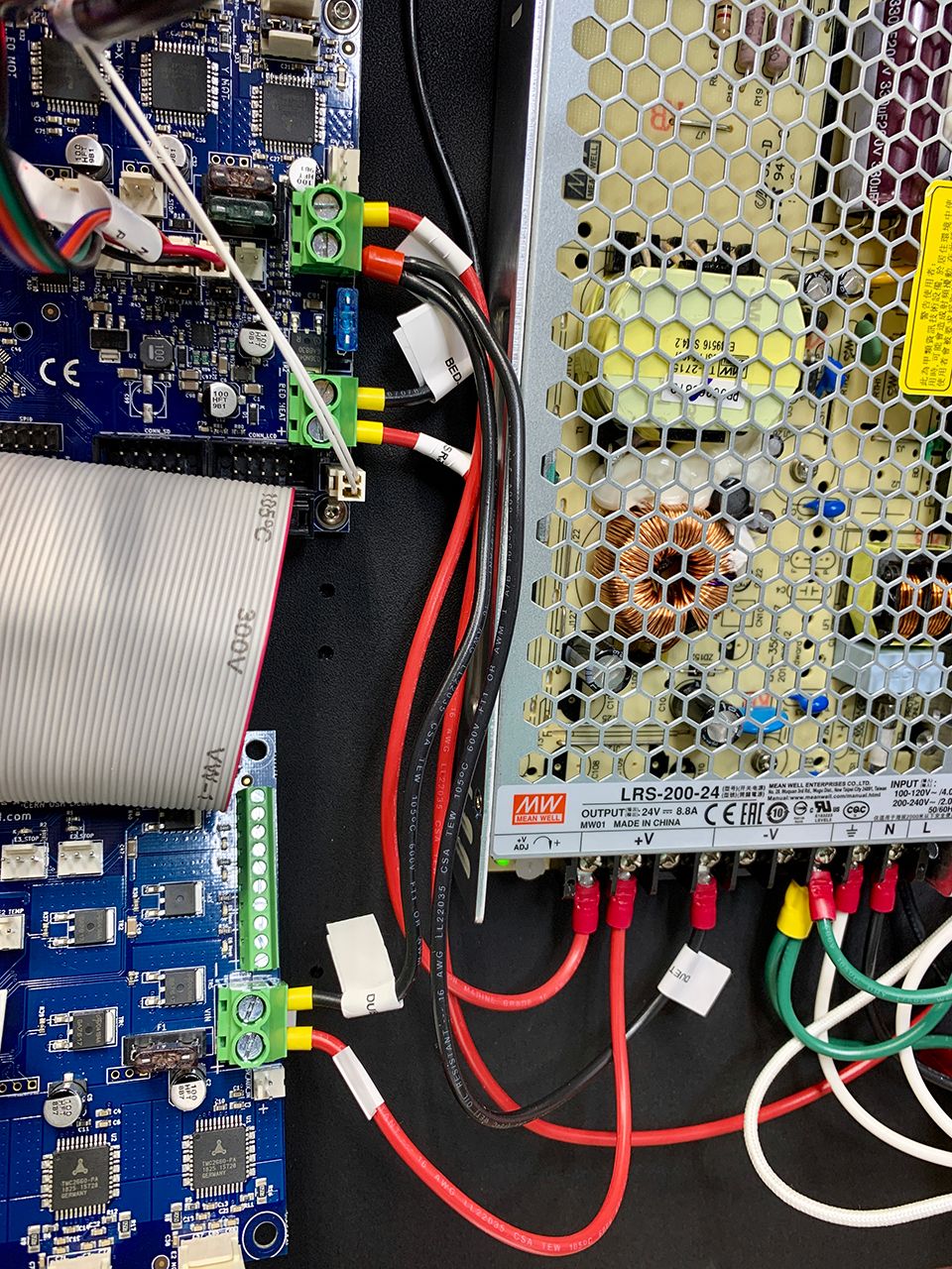
-
@BladerunnerxRC Thanks for the extra tests. I think it's not needed, but when you do get a working Duex, make sure that ALL motor settings for E take the form Exx:xx:xx:xx, not just M350; M350, M906, M201, M203, M566 and M92.
It seems like this is an SPI issue. I feel like it may be related to the ribbon cable (ie something broken or not making contact), but I've asked @dc42 to take a look at this thread.
Ian
-
Hi @BladerunnerxRC, thanks for your patience. I approve your warranty claim, so please contact Filastruder to process it. Please return to them both the DueX5 and the cable.