Duet3D Logo Duet3D
    • Tags
    • Documentation
    • Order
    • Register
    • Login

    duet 3 endstop wiring

    Scheduled Pinned Locked Moved
    Duet Hardware and wiring
    5
    33
    3.1k
    Loading More Posts
    • Oldest to Newest
    • Newest to Oldest
    • Most Votes
    Reply
    • Reply as topic
    Log in to reply
    This topic has been deleted. Only users with topic management privileges can see it.
    • A Former User?
      A Former User
      last edited by A Former User

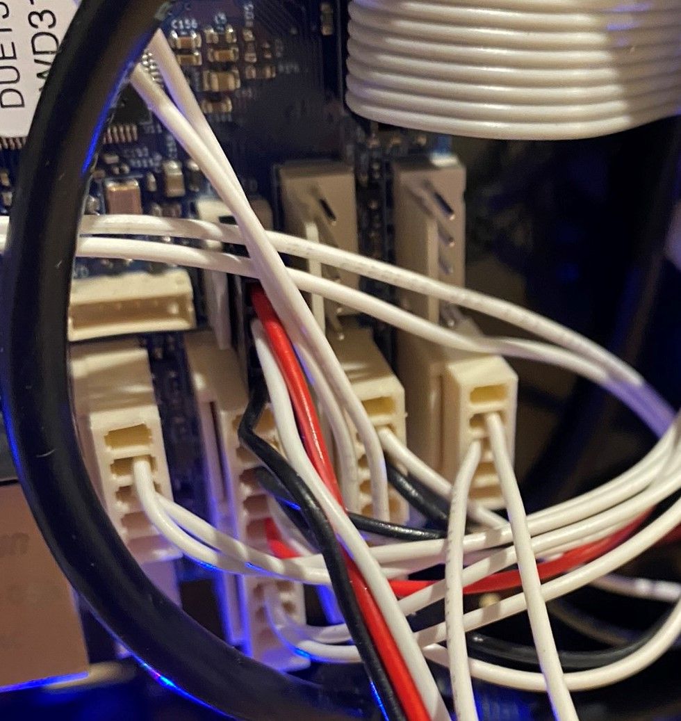
      the ground and input pin of the io0-8 headers

      although you may want to refer to https://duet3d.dozuki.com/Wiki/Duet_3_Mainboard_6HC_Hardware_Overview#Section_IO and use the io headers that doesn't have other functions you may need

      1 Reply Last reply Reply Quote 0
      • Dad003undefined
        Dad003
        last edited by

        so middle pin and the one next to it , it what i have right now but my endstop always show as triggered in the duet control , when i try to home axis move but do not hit the switch

        A Former User? 1 Reply Last reply Reply Quote 0
        • A Former User?
          A Former User
          last edited by

          normally open or normally closed switch? and how is it configured?

          1 Reply Last reply Reply Quote 0
          • Dad003undefined
            Dad003
            last edited by

            they are close switch that open when hit , duet control show then has triggered , one on each axis , at the low end excepted the Y axis

            here the switch him using

            ![https://cdn11.bigcommerce.com/s-mm9wpa/images/stencil/original/products/1204/5043/microswitch_with_1000mm_cable_800x800__94048.1506175702.jpg?c=2](image url)

            1 Reply Last reply Reply Quote 0
            • Dad003undefined
              Dad003
              last edited by

              i found something when i hold the limits switch it show as not trig erred anymore and when release it show back to triggered what parameter i show inverse ?

              1 Reply Last reply Reply Quote 0
              • A Former User?
                A Former User @Dad003
                last edited by A Former User

                @Dad003 said in duet 3 endstop wiring:

                so middle pin and the one next to it

                next to it could be ioN.out or ioN.in so pin 2 is input and pin 3 is ground to rule out ambiguity.

                also how is it configured in config.g?

                edit: ah, its configured connected correctly then. I think you need to invert the pin with the M950 command, but someone will probably confirm.

                1 Reply Last reply Reply Quote 0
                • Dad003undefined
                  Dad003
                  last edited by

                  SO WHAT SHOULD THE M950 LOOK LIKE ? SOMETHING LIKE THIS ? IN THE WIKI THERE NOT REALLY AN EXEMPLE FOR THAT KIND OF STUFF

                  M950 Jnn "IO_0" C"IO0.IN" !

                  1 Reply Last reply Reply Quote 0
                  • Danalundefined
                    Danal
                    last edited by

                    Endstops directly define their pin in m574, no M950 is used.

                    M574 X1 S1 P"io1.in" ; Set homing switch configuration X1 = low-end, S1 = active-high (NC)

                    Delta / Kossel printer fanatic

                    Dad003undefined 1 Reply Last reply Reply Quote 0
                    • Danalundefined
                      Danal
                      last edited by

                      IMG_0474 (2).jpeg

                      Delta / Kossel printer fanatic

                      1 Reply Last reply Reply Quote 0
                      • A Former User?
                        A Former User
                        last edited by

                        maybe thats just for the zprobe, and you can invert the endstop with a ! in m574 ? idk and caps locks doesn't help..

                        https://duet3d.dozuki.com/Wiki/Gcode#Section_M574_RepRapFirmware_Num_3

                        1 Reply Last reply Reply Quote 0
                        • Danalundefined
                          Danal
                          last edited by

                          Z Probe also directly defines its pin, and yes, ! and ^ work per usual:

                          M558 K0 P9 C"^io4.in" H9 A5 T6000 S0.02 ; Z probe BLtouch - Set the height of the bed when homing G28. Combined with content of bed.g as invoked by G32, levels bed. Also used for Mesh.

                          Delta / Kossel printer fanatic

                          1 Reply Last reply Reply Quote 0
                          • Dad003undefined
                            Dad003 @Danal
                            last edited by

                            @Danal

                            when i try this G code it tell me the pin is not free and nothing happen

                            1 Reply Last reply Reply Quote 0
                            • Danalundefined
                              Danal
                              last edited by

                              Then you have something else in your config.g that defines that pin, before what you are trying. There are no default assignments.

                              Did you remove the M950?

                              Delta / Kossel printer fanatic

                              1 Reply Last reply Reply Quote 0
                              • Dad003undefined
                                Dad003
                                last edited by

                                this is what i have for config file

                                ; Drives
                                M569 P0.0 S1 ; physical drive 0.0 goes forwards
                                M569 P0.1 S1 ; physical drive 0.1 goes forwards
                                M569 P0.2 S1 ; physical drive 0.2 goes forwards
                                M569 P0.5 S1 ; physical drive 0.5 goes forwards
                                M569 P0.4 S0 ; physical drive 0.4 goes forwards
                                M584 X0.0 Y0.1 Z0.2 E0.5:0.4 ; set drive mapping
                                M350 X16 Y16 Z16 E16:16 I1 ; configure microstepping with interpolation
                                M92 X160.00 Y160.00 Z6400.00 E172.64:172.64 ; set steps per mm
                                M566 X900.00 Y900.00 Z12.00 E120.00:120.00 ; set maximum instantaneous speed changes (mm/min)
                                M203 X6000.00 Y6000.00 Z180.00 E1200.00:1200.00 ; set maximum speeds (mm/min)
                                M201 X500.00 Y500.00 Z20.00 E250.00:250.00 ; set accelerations (mm/s^2)
                                M906 X800 Y800 Z800 E800:800 I50 ; set motor currents (mA) and motor idle factor in per cent
                                M84 S30 ; Set idle timeout

                                ; Axis Limits
                                M208 X0 Y0 Z0 S1 ; set axis minima
                                M208 X360 Y260 Z700 S0 ; set axis maxima

                                ; Endstops
                                M574 X1 S1 P"io0.in" ; configure active-low endstop for low end on X via pin io0.in
                                M574 Y2 S1 P"io2.in" ; configure active-low endstop for high end on Y via pin io2.in
                                M574 Z2 S1 P"io1.in" ; configure active-low endstop for low end on Z via pin io1.in

                                ; Z-Probe
                                M558 P0 H5 F120 T6000 ; disable Z probe but set dive height, probe speed and travel speed
                                M557 X15:215 Y15:195 S20 ; define mesh grid

                                ; Heaters
                                M308 S0 P"temp3" Y"thermistor" T100000 B4138 ; configure sensor 0 as thermistor on pin temp3
                                M950 H0 C"out0" T0 ; create bed heater output on out0 and map it to sensor 0
                                M143 H0 S120 ; set temperature limit for heater 0 to 120C
                                M307 H0 B1 S1.00 ; enable bang-bang mode for the bed heater and set PWM limit
                                M140 H0 ; map heated bed to heater 0
                                M308 S1 P"spi.cs0" Y"thermocouple-max31856" ; configure sensor 1 as thermocouple via CS pin spi.cs0
                                M950 H1 C"out1" T1 ; create nozzle heater output on out1 and map it to sensor 1
                                M143 H1 S260 ; set temperature limit for heater 1 to 260C
                                M307 H1 B0 S1.00 ; disable bang-bang mode for heater and set PWM limit
                                M308 S2 P"spi.cs1" Y"thermocouple-max31856" ; configure sensor 2 as thermocouple via CS pin spi.cs1
                                M950 H2 C"out2" T2 ; create nozzle heater output on out2 and map it to sensor 2
                                M143 H2 S290 ; set temperature limit for heater 2 to 290C
                                M307 H2 B0 S1.00 ; disable bang-bang mode for heater and set PWM limit

                                ; Fans
                                M950 F0 C"out7" Q500 ; create fan 0 on pin out7 and set its frequency
                                M106 P0 C"extruder 1" S1 H1 T45 ; set fan 0 name and value. Thermostatic control is turned on
                                M950 F1 C"out8" Q500 ; create fan 1 on pin out8 and set its frequency
                                M106 P1 C"extruder 2" S1 H2 T45 ; set fan 1 name and value. Thermostatic control is turned on
                                M950 F2 C"out9" Q500 ; create fan 2 on pin out9 and set its frequency
                                M106 P2 C"blower" S0 H-1 ; set fan 2 name and value. Thermostatic control is turned off
                                M950 F3 C"out6" Q500 ; create fan 3 on pin out6 and set its frequency
                                M106 P3 C"electrical" S1 H1:2 T30 ; set fan 3 name and value. Thermostatic control is turned on

                                ; Tools
                                M563 P1 D0 H1 F0 ; define tool 1
                                G10 P1 X0 Y0 Z0 ; set tool 1 axis offsets
                                G10 P1 R0 S0 ; set initial tool 1 active and standby temperatures to 0C
                                M563 P2 D1 H2 F0 ; define tool 2
                                G10 P2 X0 Y0 Z0 ; set tool 2 axis offsets
                                G10 P2 R0 S0 ; set initial tool 2 active and standby temperatures to 0C

                                ; Custom settings are not defined

                                ; Miscellaneous
                                M501 ; load saved parameters from non-volatile memory
                                M911 S10 R11 P"M913 X0 Y0 G91 M83 G1 Z3 E-5 F1000" ; set voltage thresholds and actions to run on power loss
                                T1 ; select first tool

                                A Former User? 1 Reply Last reply Reply Quote 0
                                • A Former User?
                                  A Former User @Dad003
                                  last edited by

                                  @Dad003 said in duet 3 endstop wiring:

                                  M574 X1 S1 P"io0.in" ; configure active-low endstop for low end on X via pin io0.in
                                  M574 Y2 S1 P"io2.in" ; configure active-low endstop for high end on Y via pin io2.in
                                  M574 Z2 S1 P"io1.in" ; configure active-low endstop for low end on Z via pin io1.in

                                  try
                                  M574 X1 S1 P"!io0.in"

                                  and so on

                                  Dad003undefined 1 Reply Last reply Reply Quote 0
                                  • Dad003undefined
                                    Dad003
                                    last edited by

                                    my endstop are assigne to io_0 , io_1 and io_2

                                    1 Reply Last reply Reply Quote 0
                                    • A Former User?
                                      A Former User
                                      last edited by

                                      note the exclamation point before the pin name, should invert the pin so its active when pressed instead of the other way around.

                                      1 Reply Last reply Reply Quote 0
                                      • Dad003undefined
                                        Dad003 @A Former User
                                        last edited by

                                        @bearer said in duet 3 endstop wiring:

                                        M574 X1 S1 P"!io0.in"

                                        thank you , that solved my problem !

                                        and another problem gone , now i need to figure out why the bed heat so slow

                                        1 Reply Last reply Reply Quote 0
                                        • Dad003undefined
                                          Dad003
                                          last edited by

                                          so here another development after finally having the limit switch in the right state , trying to home the axis , X will move and do what need to be done , Y will move but not hit the switch or ram into the switch without stopping and say it home and the Z axis will move like 10mm and nothing else without even ever getting close of the switch

                                          him using the basic g code from the RRF Config tool, i even copy pasted the X home code that was working and switching the coordinate and axis and it still doesnt work

                                          ; homeall.g
                                          ; called to home all axes
                                          ;
                                          ; generated by RepRapFirmware Configuration Tool v2.1.8 on Sun May 03 2020 01:01:37 GMT-0600 (Mountain Daylight Time)
                                          G91 ; relative positioning
                                          G1 H2 Z-5 F3000 ; lift Z relative to current position
                                          G1 H1 X-365 Y255 F1800 ; move quickly to X and Y axis endstops and stop there (first pass)
                                          G1 H2 X5 Y-5 F3000 ; go back a few mm
                                          G1 H1 X-365 Y255 F360 ; move slowly to X and Y axis endstops once more (second pass)
                                          G1 H1 Z-805 F360 ; move Z down stopping at the endstop
                                          G90 ; absolute positioning
                                          G92 Z0 ; set Z position to axis minimum (you may want to adjust this)

                                          ; Uncomment the following lines to lift Z after probing
                                          ;G91 ; relative positioning
                                          ;G1 Z-5 F50 ; lift Z relative to current position
                                          ;G90 ; absolute positioning

                                          1 Reply Last reply Reply Quote 0
                                          • dc42undefined
                                            dc42 administrators
                                            last edited by

                                            Please reset the homing files to the ones the the configurator generated, and post them here along with your current config.g file.

                                            Duet WiFi hardware designer and firmware engineer
                                            Please do not ask me for Duet support via PM or email, use the forum
                                            http://www.escher3d.com, https://miscsolutions.wordpress.com

                                            Dad003undefined 1 Reply Last reply Reply Quote 0
                                            • First post
                                              Last post
                                            Unless otherwise noted, all forum content is licensed under CC-BY-SA