Duet 2 Ethernet 12V Fan wiring
-
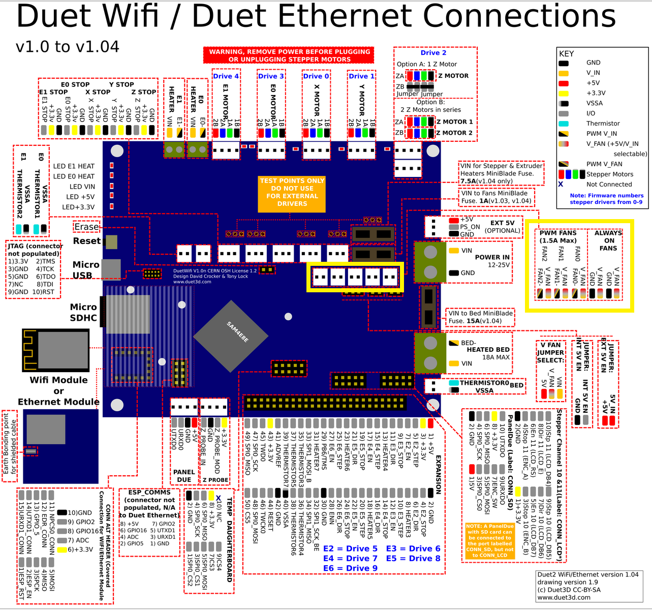
What pins are you actually checking? There is nothing labeled port 1 2 3 4 5, so I'm not sure what you're measuring.
-
@Phaedrux said in Duet 2 Ethernet 12V Fan wiring:
What pins are you actually checking? There is nothing labeled port 1 2 3 4 5, so I'm not sure what you're measuring.
I measured the yellow framed FAN pins.

-
Ok, and how are your fans configured when you're measuring them?
-
@Phaedrux said in Duet 2 Ethernet 12V Fan wiring:
Ok, and how are your fans configured when you're measuring them?
So far I have only connected the buck converter to the 12V + pin on the jumper slot as shown in the top picture. I have not yet made another active config in the firmware.
-
Ok well you can't measure anything usable off the fan ports unless you have configured them. The always on fan ports should measure with the same voltage as the Vfan pin is being fed.
-
@Phaedrux said in Duet 2 Ethernet 12V Fan wiring:
Ok well you can't measure anything usable off the fan ports unless you have configured them. The always on fan ports should measure with the same voltage as the Vfan pin is being fed.
Ah OK I understand. So I have to configure each fan individually. Do you have any instructions on how to configure the fans for the 12 V?
-
Actually, I would like to have all fan slots on 12 V, 4 of them always switched on and a space for the component fan running on software PWM.
-
Well it depends on your firmware version, but the easiest thing to do would be to go through the web configurator to get your fan configuration to test.
https://configtool.reprapfirmware.org/Start
In RRF2 the fan pins are pre-defined and you only need control them with an M106 command.
https://duet3d.dozuki.com/Wiki/Gcode#Section_M106_Fan_OnIn RRF3 you need to define the fan pins with M950 commands and then use an M106 to control them.
Since you are providing 12v to the Vfan pin, all the fans will be 12v. Fan0,1, 2 are PWM controllable, and then there are 2 always on fan ports.
Here's a basic config for RRF3 from the configurator.
; Fans
M950 F0 C"fan0" Q500                           ; create fan 0 on pin fan0 and set its frequency
M106 P0 S0 H-1                                 ; set fan 0 value. Thermostatic control is turned off
M950 F1 C"fan1" Q500                           ; create fan 1 on pin fan1 and set its frequency
M106 P1 S1 H1 T45                              ; set fan 1 value. Thermostatic control is turned on
M950 F2 C"fan2" Q500                           ; create fan 2 on pin fan2 and set its frequency
M106 P2 S1 H-1                                 ; set fan 2 value. Thermostatic control is turned off
Fan 0 is the default for the part cooling fan and is controlled by the slicer.
Fan1 is the default for the hotend fan and is controlled by the hotend temp. Turns on over 45c.
Fan 2 is whatever you want and can be manually controlled or thermostatically controlled.
Then the 2 always on fan ports are always on. -
Great, that just helped me.
Now all fan positions are switched to 12V.Thanks for the support.
-
Any time.