Wire combining for tool head
-
After looking over some of the threads on here about combining wires I wanted to get everyone's opinion on this wire layout as a sanity check to make sure I am thinking correctly.
I am designing a direct drive extruder for my tool change printer and can only fit a DB9 connector and need to fit all these wires.
Heater
Thermistor
Heatsink Fan
Part cooling Fan
Filament runout
Does this diagram look correct?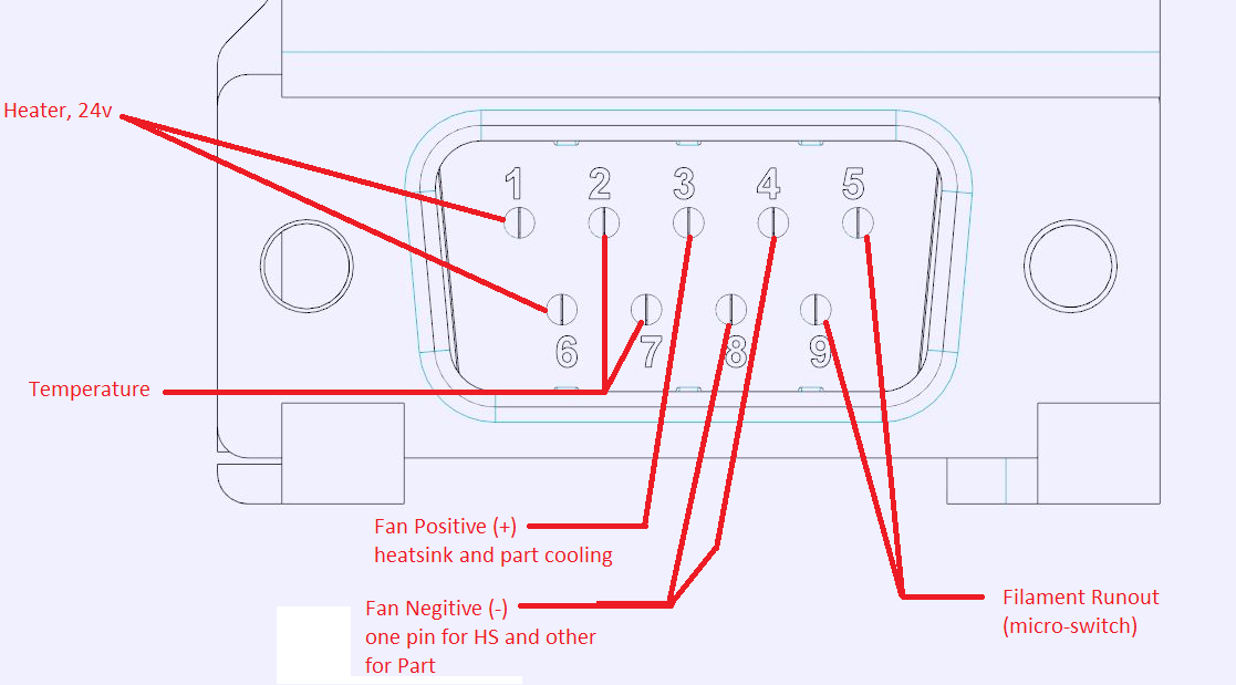
-
A direct extruder also needs four more wires for the stepper, so DB9 won't cut it. You'd need at least DB15.
An interesting design I encountered last summer was using an 11W1 connector (more photos of the connector type at https://www.sgconnector.com/conn/11w1-male-mixed-contact-d-type-connector), but that still is missing connectors for a direct extruder stepper, and will only barely fit a Z Probe. But it gives you a removable PTFE tube to feed the filament. A D-Sub 21W1 would give you
- 4x stepper
- 2x thermistor
- 2x heater cartridge
- 2x part cooling fan
- 2x hotend fan
- 2x filament runout sensor
- 3x z probe
Depending on whether you trust single pins to take the load, you have two more pins to double up the connections for your heater. If you want to add an LED to the print tool, you can share ground with the hotend fan similar to the way it's setup on the Duet3D Smart Effector.
-
I would put the heater and fan wires at one end assuming they are all the same voltage, then the thermistor wires, and the microswitch wires at the other. This should somewhat reduce the risks of damage due to short circuits between the high- and low-voltage circuits.
It's to avoid this type of wiring complexity that we introduced the Duet 3 Tool Board.
Duet WiFi hardware designer and firmware engineer
Please do not ask me for Duet support via PM or email, use the forum
http://www.escher3d.com, https://miscsolutions.wordpress.com -
@dc42 Currently the fans are 12v because I am using the Noctua 40mm fans and they do not come in 24v versions. Am I correct in thinking that the switching for the fans is done on the GND though?
@oliof I am currently using a 15 conductor cable and have the wires for the stepper coming out separate from the DB connector. I would prefer to have them in the connector but the DB15 connectors that I bought ware just so big that it really compromised the design intent of the extruder. Here is how I am currently running.
15 conductors:
4 for heater
2 for Thermistor
2 for HS Fan
2 for Part Fan
4 for Stepper
That comes to 14 of the 15 used. So now I have come up with a way to add a filament runout sensor built into the extruder just above the drive gears so I was thinking if I can use just one power wire for the fans that will free up one more wire to have two free.
Here are some pictures of my design. It is based on a bondtech BMG but is a highly modified design.With tool plate
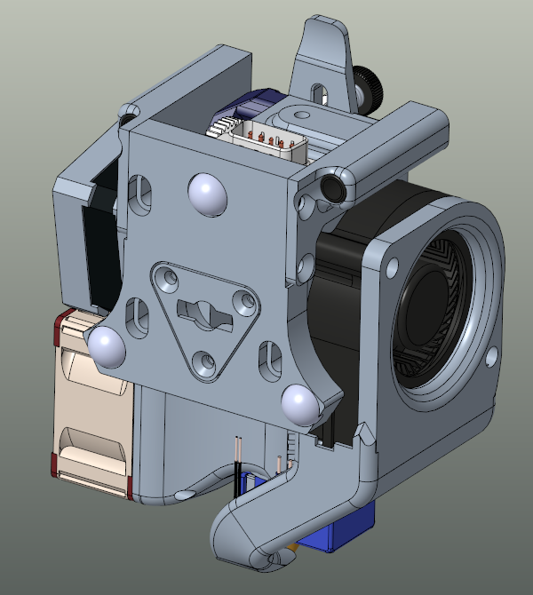
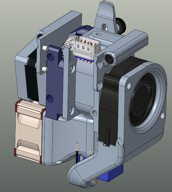
Tool plate removed you can see the DB9 connector
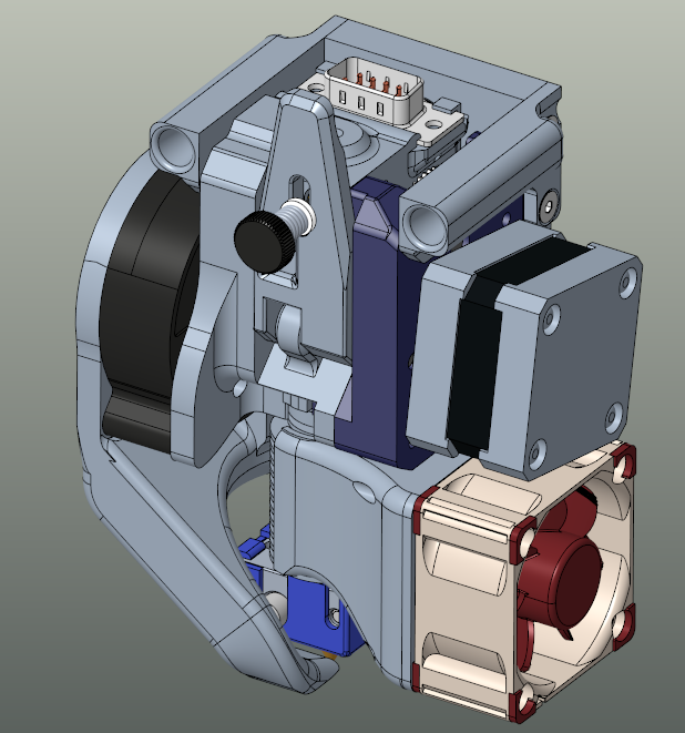
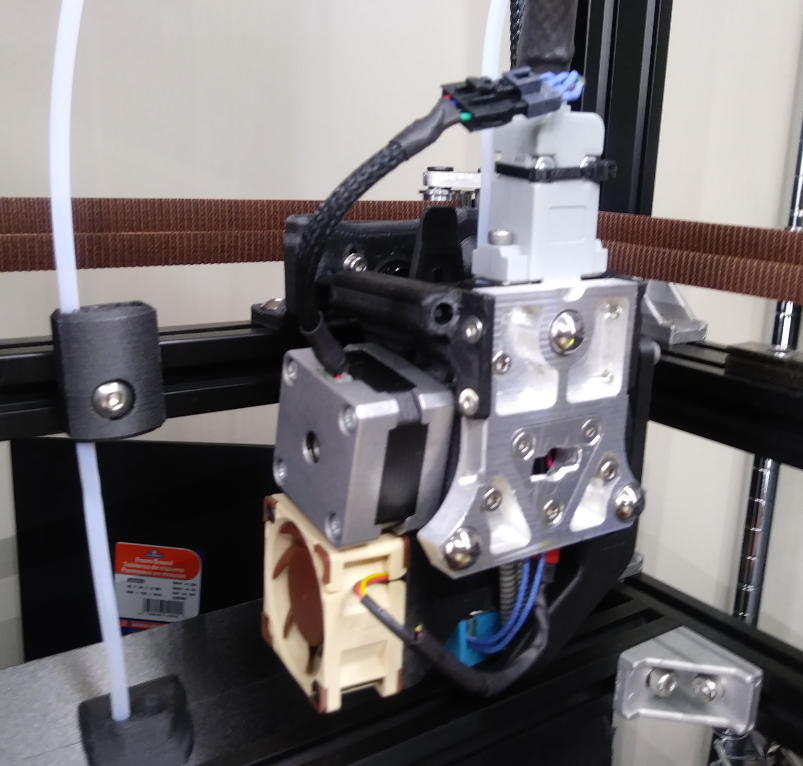
This is still in the prototype phase and have been refining the design over the past few months but I have been printing with no issues now for about two months and been able to print PC with no jams or heat creep.
The tool mounting and locking system is based on a design by PoofJunior over on Thingiverse that he did for his Jubilee printer.