RepPanel - A DIY alternative to the PanelDue with WiFi support
-
@pandaym Your hardware looks good to me! The DevBoard is standard so that's perfectly fine. The screen is tricky but it should work. Its touch controller is a XPT2046 which definitely supported by LVGL. I did some searching and my best guess is that the display is from waveshare. Looking at their driver code the chip should be a ILI9486 which is also supported by LVGL and thus by RepPanel

-
@seeul8er said in RepPanel - A DIY alternative to the PanelDue with WiFi support:
@pandaym Your hardware looks good to me! The DevBoard is standard so that's perfectly fine. The screen is tricky but it should work. Its touch controller is a XPT2046 which definitely supported by LVGL. I did some searching and my best guess is that the display is from waveshare. Looking at their driver code the chip should be a ILI9486 which is also supported by LVGL and thus by RepPanel
Thanks a lot, that sounds good! I will dive into it and see if I can figure out how to wire and program it
")
-
Any 5 inch screens witch could run with LVGL?
-
@dragonn said in RepPanel - A DIY alternative to the PanelDue with WiFi support:
Any 5 inch screens witch could run with LVGL?
I am afraid not. With 5" screens the resolution usually is not 480x320 anymore. The RepPanel UI is sort of hardcoded for that resolution since it is an embedded system. Besides that, the ESP32 with SPI is not powerful enough to updated higher-resolution screens in time.
-
@pandaym said in RepPanel - A DIY alternative to the PanelDue with WiFi support:
@seeul8er said in RepPanel - A DIY alternative to the PanelDue with WiFi support:
@pandaym Your hardware looks good to me! The DevBoard is standard so that's perfectly fine. The screen is tricky but it should work. Its touch controller is a XPT2046 which definitely supported by LVGL. I did some searching and my best guess is that the display is from waveshare. Looking at their driver code the chip should be a ILI9486 which is also supported by LVGL and thus by RepPanel
Thanks a lot, that sounds good! I will dive into it and see if I can figure out how to wire and program it
@seeul8er any chance I could get some help finding the right way to wire it? I have started, but I got stuck trying to figure out the naming and what was what.
So I got:
ESP > LCD:
3.3V > Pin 1
GND > Pin 6
GPIO 13 > Pin 19 (MOSI - Data line to TFT)
GPIO 14 > Pin 23 (SCL - SPI CLK for TFT)
GPIO 15 > ?!?!? (Slave Select - SPI)
GPIO 22 > ?!?!? (SCL - I2C - touch)
GPIO 21 > ?!?!? (SDA - I2C - touch)
GPIO 4 > Pin 22 (Reset - TFT related)
GPIO 2 > ?!?!? (Data - TFT related)
GPIO 27 > ?!?!? (Backlight - Turn on/off TFT backlight)
And lastly I got GPIO 17 and 16 that will go to the Duet
Mind helping me figure out where the last ones go?
-
Your touch screen is connected via a second SPI. Mine is I²C. The second SPI and all other pins will be a config thing during compilation (menuconfig settings) The default for LVGL should be the following HSPI for TFT and VSPI for the touch controller - I think you can choose the "RPi MPI3501" config during the build. The pins can be selected/changed but this should work:
GPIO 15 -> 24 (Slave/Chip select for TFT)
GPIO 23 -> 19 MOSI Touch - (but should not be needed?!)
GPIO 19 -> 21 MISO Touch
GPIO 18 -> 23 CLK Touch (same clk for touch and tft)
GPIO 5 -> 26 Chip select Touch
GPIO 25 -> 11 Interrupt Touch
GPIO 2 -> 18Looks like the backlight is on automatically
-
@seeul8er said in RepPanel - A DIY alternative to the PanelDue with WiFi support:
Your touch screen is connected via a second SPI. Mine is I²C. The second SPI and all other pins will be a config thing during compilation (menuconfig settings) The default for LVGL should be the following HSPI for TFT and VSPI for the touch controller - I think you can choose the "RPi MPI3501" config during the build. The pins can be selected/changed but this should work:
GPIO 15 -> 24 (Slave/Chip select for TFT)
GPIO 23 -> 19 MOSI Touch - (but should not be needed?!)
GPIO 19 -> 21 MISO Touch
GPIO 18 -> 23 CLK Touch (same clk for touch and tft)
GPIO 5 -> 24 Chip select Touch
GPIO 25 -> 11 Interrupt Touch
GPIO 2 -> 18
Looks like the backlight is on automaticallyThanks a lot for the help. I apologize, but I am a complete newbie in all of this stuff, so it is a bit much to chew
Wonder if I understand it correctly. So I still use the pins for 3.3v, gnd and reset like I set them, and add the ones you mentioned? This should make the full wiring this:
ESP > LCD:
3.3V -> Pin 1
GND -> Pin 6
GPIO 4 -> Pin 22 (Reset - TFT related)
GPIO 15 -> 24 (Slave/Chip select for TFT)
GPIO 23 -> 19 MOSI Touch - (but should not be needed?!)
GPIO 19 -> 21 MISO Touch
GPIO 18 -> 23 CLK Touch (same clk for touch and tft)
GPIO 5 -> 24 Chip select Touch
GPIO 25 -> 11 Interrupt Touch
GPIO 2 -> 18And ESP > Duet 3:
GPIO 16 -> TX PanelDue port
GPIO 17 -> RX PanelDue portDoes this mean I have to bridge it so that both GPIO 15 and GPIO 5 go to the 24 pin on the screen?
-
@pandaym Sorry my bad. Chip select for the touch must be GPIO 5 -> 26. I corrected it.
Yes. Looks good! All in all its just about knowing SPI wiring in general and then matching the inputs & outputs. The software/compile process will allow you to change some GPIOs, but with this most stuff should already be configured correctly.
-
@seeul8er said in RepPanel - A DIY alternative to the PanelDue with WiFi support:
@pandaym Sorry my bad. Chip select for the touch must be GPIO 5 -> 26. I corrected it.
Yes. Looks good! All in all its just about knowing SPI wiring in general and then matching the inputs & outputs. The software/compile process will allow you to change some GPIOs, but with this most stuff should already be configured correctly.
Arh, thanks! Really appreciate you helping me out!
I guess my challenge is I don't even know wiring in general, let alone SPI wiring.
So this is how I wired it now:
ESP > LCD:
3.3V -> Pin 1
GND -> Pin 6
GPIO 4 -> Pin 22 (Reset - TFT related)
GPIO 15 -> 24 (Slave/Chip select for TFT)
GPIO 23 -> 19 MOSI Touch - (but should not be needed?!)
GPIO 19 -> 21 MISO Touch
GPIO 18 -> 23 CLK Touch (same clk for touch and tft)
GPIO 5 -> 26 Chip select Touch
GPIO 25 -> 11 Interrupt Touch
GPIO 2 -> 18Connection to the Duet, as far as I understand, can be done either wirelessly or wired like this, right?
GPIO 16 -> TX PanelDue port (which I assume on a Duet 3 is IO_0_out ?)
GPIO 17 -> RX PanelDue port (which I assume on a Duet 3 is IO_0_in ?)The controllers you mentioned seems to be right according to this: http://www.lcdwiki.com/3.5inch_RPi_Display , so ILI9486 and XPT2046.
So to get started on the software side I:
- Installed ESP-IDF
- Cloned the project
- Replaced the contents of externals/lv_port_esp32/components/lvgl/lv_conf.h with that of main/lv_conf_back.h
- Ran idf.py menuconfig
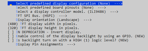
So for TFT display controller I have it set up like this for starters:
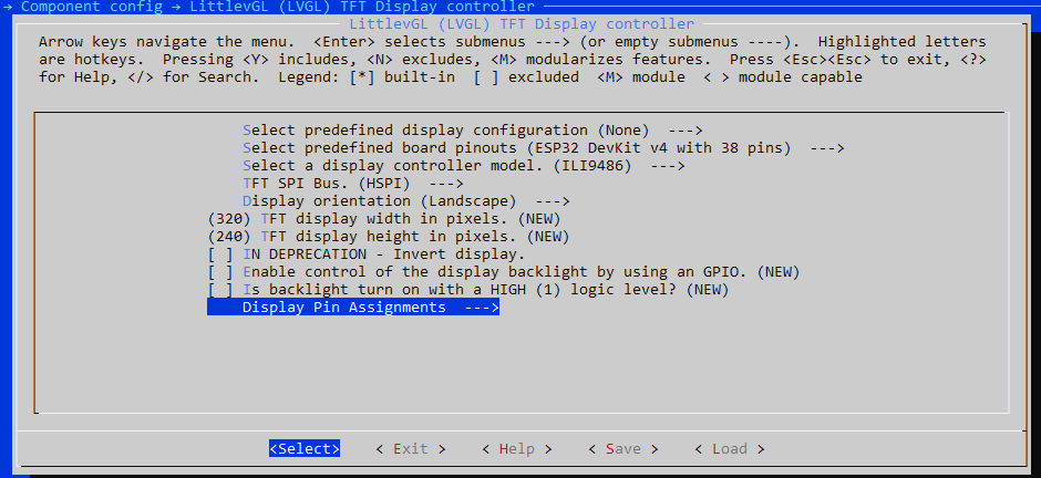
I hope it is correctly assumed that there is nothing pre-defined, so I have to do it like that. For the board pinouts, it looks like ESP32 V4 with 38 pins should be correct for the ESP32-DevKitC-32D ?
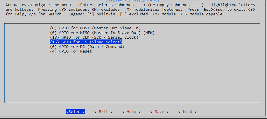
Then I just chose ILI9486 and left the rest of the main page as is.For the pin-out I have this, but I don't know if something is missing or wrong here?
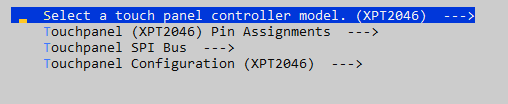
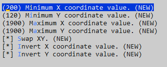
Touch controller I set up like this:
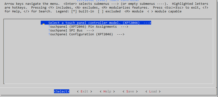
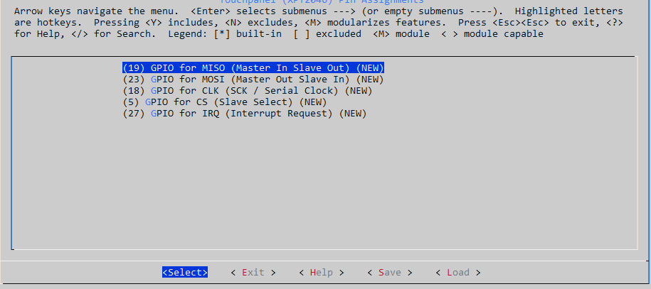
With this assignment:
Last thing is the WiFi connection. I cannot tell where I add my SSID and password for it. Am I overlooking something?
-
Make sure you checkout the LVGL repo at exactly this commit:
git checkout c1f43bfb090df293059ab52baabbdbdd8df00712The predefined board pinout does not matter. You can set it to manual/None. Just make sure the pins for TFT and touch are defined exactly the way you plan on wiring them.
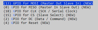
You have two separate SPI connections. One for the TFT and one for the touch controller. So the "0" in your display pin assignment are wrong since MOSI must be 13, MISO does not matter I think, DC (Data) must be 2 - just as we said above.
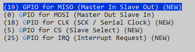
The touch pin config looks good. But you wired GPIO 25 for IRQ (interrupt) - go change it from 27 to 25 then or rewire")
Adjust the TFT pixel resolution (480x320).Yes. I think you got the duet UART config right. Otherwise switch the cables
The SSID & password are set via the RepPanel GUI once compiled and flashed.
-
@seeul8er said in RepPanel - A DIY alternative to the PanelDue with WiFi support:
Make sure you checkout the LVGL repo at exactly this commit:
git checkout c1f43bfb090df293059ab52baabbdbdd8df00712Once again thank you.
After having sort of found out what commits are etc. I hope I found out the way to check it out at that. Is it correct that after cloning I navigate to RepPanel_ESP32\externals\lv_port_esp32 and run the "git checkout c1f43bfb090df293059ab52baabbdbdd8df00712". This gives me the following message:
HEAD is now at c1f43bf Merge pull request #139 from an-erd/fix_mono_dispHave I gotten that right?
@seeul8er said in RepPanel - A DIY alternative to the PanelDue with WiFi support:
You have two separate SPI connections. One for the TFT and one for the touch controller. So the "0" in your display pin assignment are wrong since MOSI must be 13, MISO does not matter I think, DC (Data) must be 2 - just as we said above.
Alright, I understand most of that now. I have just rearranged the wiring according to the config to make it easier to see the correlation. It seemed as then I was missing the MOSI for TFT. I have tried to rework it, hopefully this sorts it out:
Full Wiring - ESP -> LCD
Power:
3.3V -> Pin 1
GND -> Pin 6TFT:
GPIO 13 -> 19 MOSI
GPIO 18 -> 23 Serial Clock (Shared between TFT and Touch)
GPIO 15 -> 24 - Slave select
GPIO 2 -> 18 - Data
GPIO 4 -> Pin 22 - Reset
Touch:
GPIO 19 -> 21 MISO
GPIO 18 -> 23 Serial Clock (Shared between TFT and Touch)
GPIO 5 -> 26 Slave select
GPIO 25 -> 11 IRQ
Other than that I got:
Touch controller:

Display controller:
Am I getting there?
-
I thought I would just give it a try to see if something showed up. So I:
- Saved the configuration in the menuconfig
- Ran idf.py build
- Connected USB to the ESP32 and found that it was on COM9
- Ran idf.py -p COM9 flash
Unfortunately, the display never came on. So I wondered if it needed power on other pins and used my multimeter to check. I could see that the two 3.3V pins on the screen are internally connected, so are the two 5V pins and the five ground pins.
So I thought that it probably needs both 5V and 3.3V, so I wired 5V from the ESP32 to pin 2 on the screen.
When I plugged USB back in, the screen lit up, but nothing happened:

-
@pandaym Your config looks good now. Yes you got the commit thing right. Otherwise you'd get a compile error.
Can you check the debug log please? You can do that by running:idf.py monitorThe 5V & 3.3V thing is strange. I'll take a look at the data sheet later.
-
@seeul8er Thanks for your reply. I had in fact bought the LCD but the resistive touch version. I've been waiting for the capacitive one to come so that I can have another try. Would there be much reprogramming needed to use the resistive touch version?
-
@pd said in RepPanel - A DIY alternative to the PanelDue with WiFi support:
@seeul8er Thanks for your reply. I had in fact bought the LCD but the resistive touch version. I've been waiting for the capacitive one to come so that I can have another try. Would there be much reprogramming needed to use the resistive touch version?
Not at all, but you'll need to compile and flash the image yourself. Choose the XPT2046 chip as a touch screen controller and the ILI9488 for TFT in "idf.py menuconfig" and set the pins you want to use (take a look at above posts for the XPT2046 & the RepPanel repo for TFT related pins). After that check the datasheet of the display and connect the wires accordingly (You'll have two SPIs - TFT and touch). For the TFT related GPIOs you can use my config. Only the touch controller will be different.
-
@seeul8er said in RepPanel - A DIY alternative to the PanelDue with WiFi support:
@pandaym Your config looks good now. Yes you got the commit thing right. Otherwise you'd get a compile error.
Can you check the debug log please? You can do that by running:idf.py monitorThe 5V & 3.3V thing is strange. I'll take a look at the data sheet later.
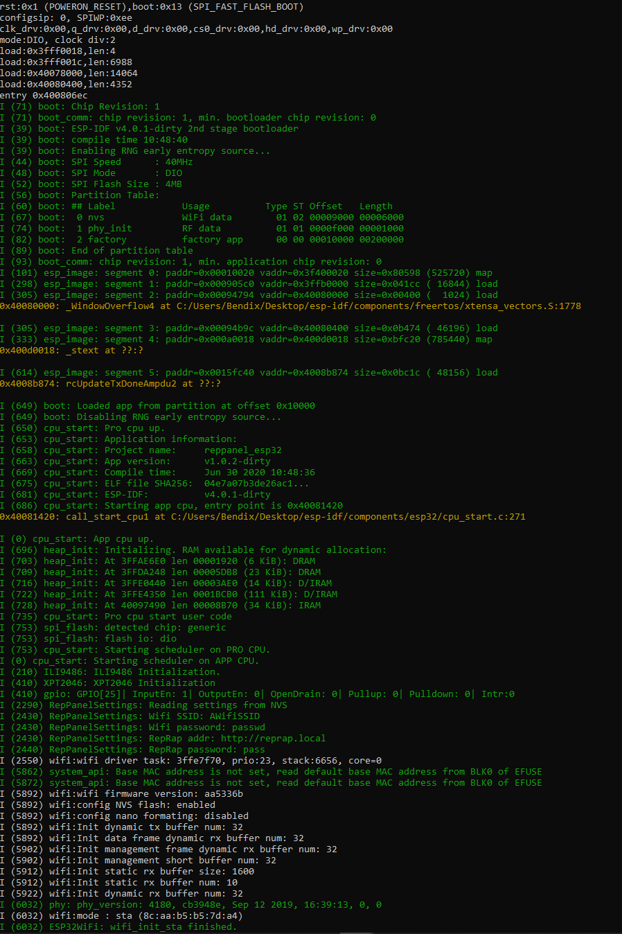
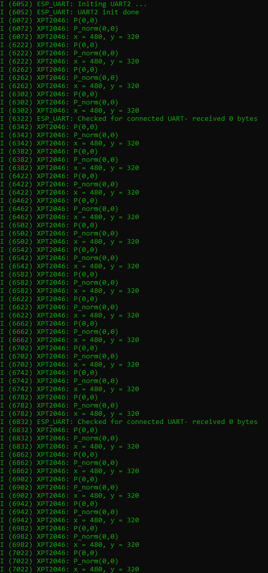
I ran idf.py monitor, and it looks like something from the Matrix. Still haven't gotten anything on screen.

-
@pandaym Check the docs on that. Further down it says changing the Main XTAL frequency might solve the output issue. Maybe autodetect does the trick.
-
@seeul8er said in RepPanel - A DIY alternative to the PanelDue with WiFi support:
@pandaym Check the docs on that. Further down it says changing the Main XTAL frequency might solve the output issue. Maybe autodetect does the trick.
Same thing regardless of XTAL frequency. I rebuilt and reflashed between attempting them. Then I disconnected all my wiring to run the ESP32 on its own, still no luck.
I then navigated to the examples and tried to build and flash the hello world example - this works fine:
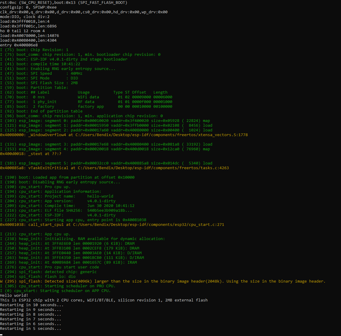
I went through the menuconfig on this vs. RepPanel, and found some differences in flash size and baud rate for monitor. I changed the Flash size to 2 like on Hello World, but then it would not flash because of insufficient space. I then tried changing idf.py monitor baud rate to 115200, while keeping 4mb flash size, and then I got monitor running:
Shall I try and wire it back up? Also, what do you think I have to do about power? Still haven't figured whether I should need to connect both a 5V and a 3.3V cable from the ESP32 to the screen.
-
@pandaym said in RepPanel - A DIY alternative to the PanelDue with WiFi support:
Shall I try and wire it back up? Also, what do you think I have to do about power? Still haven't figured whether I should need to connect both a 5V and a 3.3V cable from the ESP32 to the screen.
Try using only the 5V input. I am pretty sure you do not need both.
Looking at the logs I'd say that the flash and startup of RepPanel were a success. I'd go wire it up again. Can only be a GPIO config or wiring issue.
Does your display feature any switches/bridged pins? Read something about that in the forums. -
@seeul8er said in RepPanel - A DIY alternative to the PanelDue with WiFi support:
@pandaym said in RepPanel - A DIY alternative to the PanelDue with WiFi support:
Shall I try and wire it back up? Also, what do you think I have to do about power? Still haven't figured whether I should need to connect both a 5V and a 3.3V cable from the ESP32 to the screen.
Try using only the 5V input. I am pretty sure you do not need both.
Looking at the logs I'd say that the flash and startup of RepPanel were a success. I'd go wire it up again. Can only be a GPIO config or wiring issue.
Does your display feature any switches/bridged pins? Read something about that in the forums.Still no luck unfortunately.
I tried wiring it up to a Raspberry, just to confirm that it works. And that worked fine.
Must be a wiring issue, but I cannot find any diagram for it anywhere, I have just been counting them out and using their table.