Duet 3 2-Wire Fan Help
-
Hello!
I'm trying to get my fans (hot end and layer) working for my new build and can't figure it out. This is for a Duet3 so the docs still seem a bit thin.
They're both 2 wire fans, connected to the top two pins of OUT4 and OUT5. (GND and V_OUTLC1) This is what I understood to be correct from the following instructions on the Duet3 Wiring Guide:
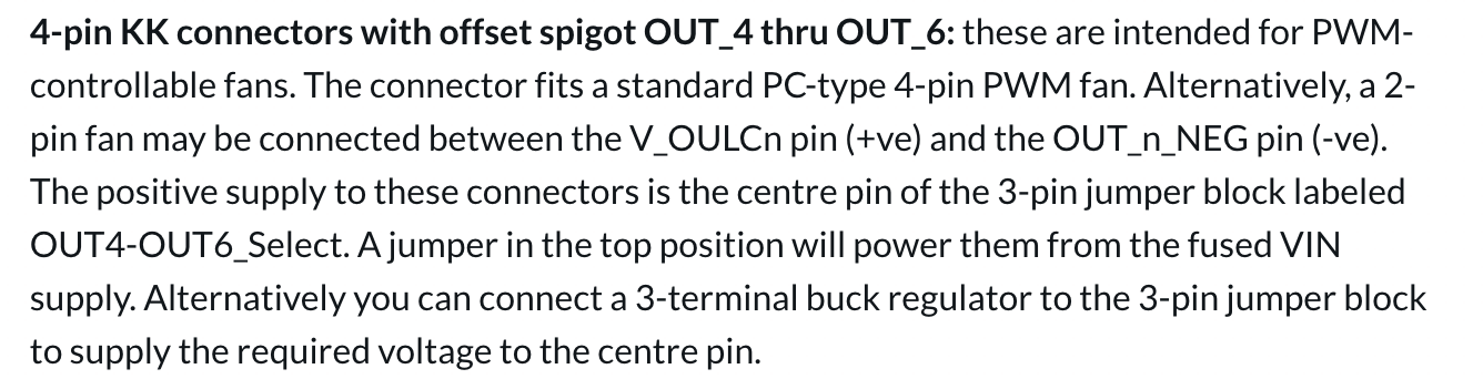
4-pin KK connectors with offset spigot OUT_4 thru OUT_6: these are intended for PWM-controllable fans. The connector fits a standard PC-type 4-pin PWM fan. Alternatively, a 2-pin fan may be connected between the V_OULCn pin (+ve) and the OUT_n_NEG pin (-ve).
The fans come on, but they're always at 100% and I can't get them to turn off or modulate the speed at all.
Any thoughts?
Here's my config:
; Fans
M950 F0 C"out5" ;Hotend fan on "out5" connector
M106 P0 S255 H1 T50 ;enable thermostatic mode for hotend fan
M950 F1 C"out4" ;Layer fan on "out4" connector
M106 P1 S0 ;Layer Fan -
-
@bearer Ah HA!
If someone who edits the docs is watching, I found the description to be super confusing...
-
You're clearly not the first; but if you can be a little more specific about which part was confusing the guy editing stands a better chance of making it clearer.
-
Fair enough...
After reading this:
And looking at this:
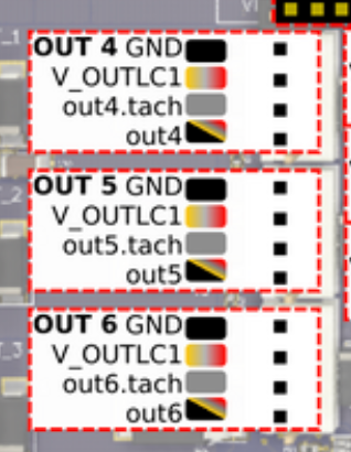
I had to figure out where to connect the wires.
For the positive leg, V_OULCn clearly maps to the V_OUTLC1 pins in the picture. That said there's a typo. The doc should read V_OUTLCn not V_OULCn.
I was confused about the ground leg. The text "OUT_n_NEG pin (-ve)" from the doc doesn't map to specific text in the drawing. The closest looking one is OUT 6 GND so I went with that. If the doc read that it should go to outn it would be clearer.
