@dc42 Ah! Thank you. I'll mess with that.
Latest posts made by benha
-
Chamber Heater Controlposted in General Discussion
Hi.
I have a large chamber volume, and it takes a fairly long time for it to come up to temperature. I've been unable to get the DWC to successfully control it, because it times out before noticing an appreciable difference in temperature. Even the PID tuning routine does this. Is there a way to configure a heater as "best effort" or something so it doesn't abort the print if the temp isn't achieved?
-Ben
-
RE: Mesh Bed Leveling expected behaviorposted in General Discussion
Ok. Made these changes and I'm still having issues.
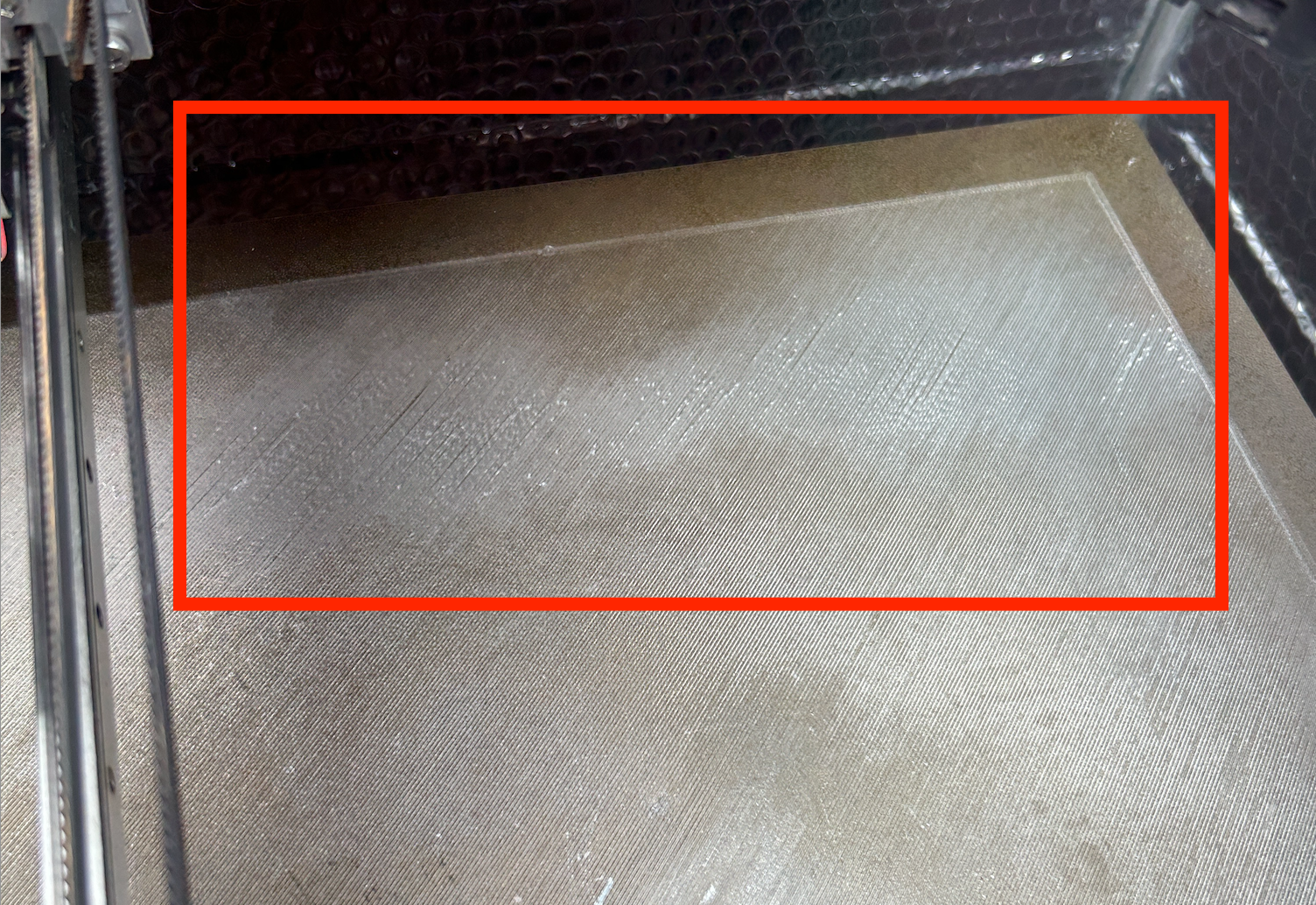
As you can see in the attached image, the layer deposition in the back corner of the plate is poor. To my eye it seems the only explanation is that the gap between the nozzle and the bed is widening, resulting in poor bed adhesion, and also gaps between the filament lines.
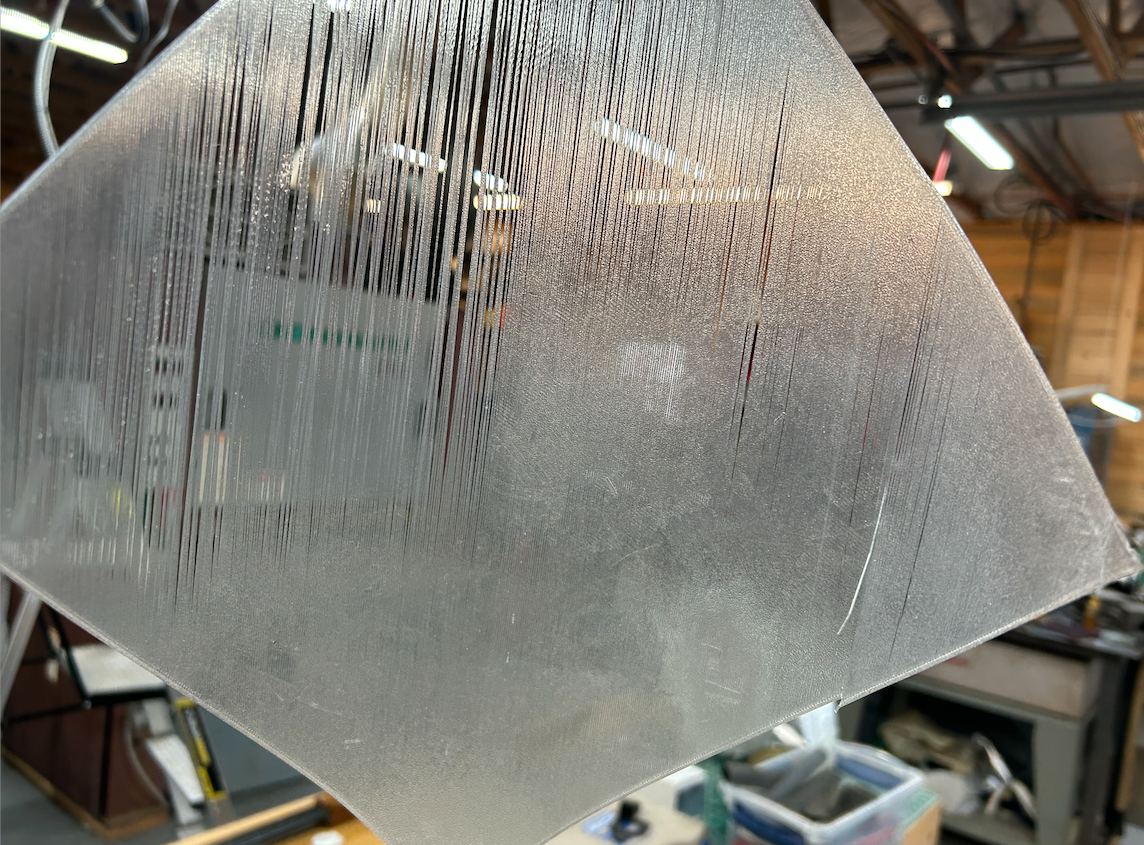
When I remove this from the plate, I see some areas where things are fully fused into a sheet, and others where they're not. Again, the only thing I can think of to explain this is that in bed areas which are closer to the nozzle as it prints there's more squeeze forcing things together, and in other areas the nozzle is further away resulting in this issue.
Thoughts?
-
RE: Mesh Bed Leveling expected behaviorposted in General Discussion
Thank you! Let me mess with this and see if I can get things going correctly. I'm out of town for a few days but I'll revert back when I've tested it.
The Orth. Axis Comp. eval / tuning was something the Railcore setup guide recommended. Intuitively it makes sense that you're not going to have perfect perpendicularity between the X and Y axis mechanicals, right? I mostly print engineering parts so getting things to print angles in the x-y plane as correctly as possible is important to me.
-
RE: Mesh Bed Leveling expected behaviorposted in General Discussion
Ah. Right. Took me a minute to figure out which files you were talking about!
-
RE: Mesh Bed Leveling expected behaviorposted in General Discussion
Thanks for taking an interest! This is a Railcore ZLT I built several years ago.
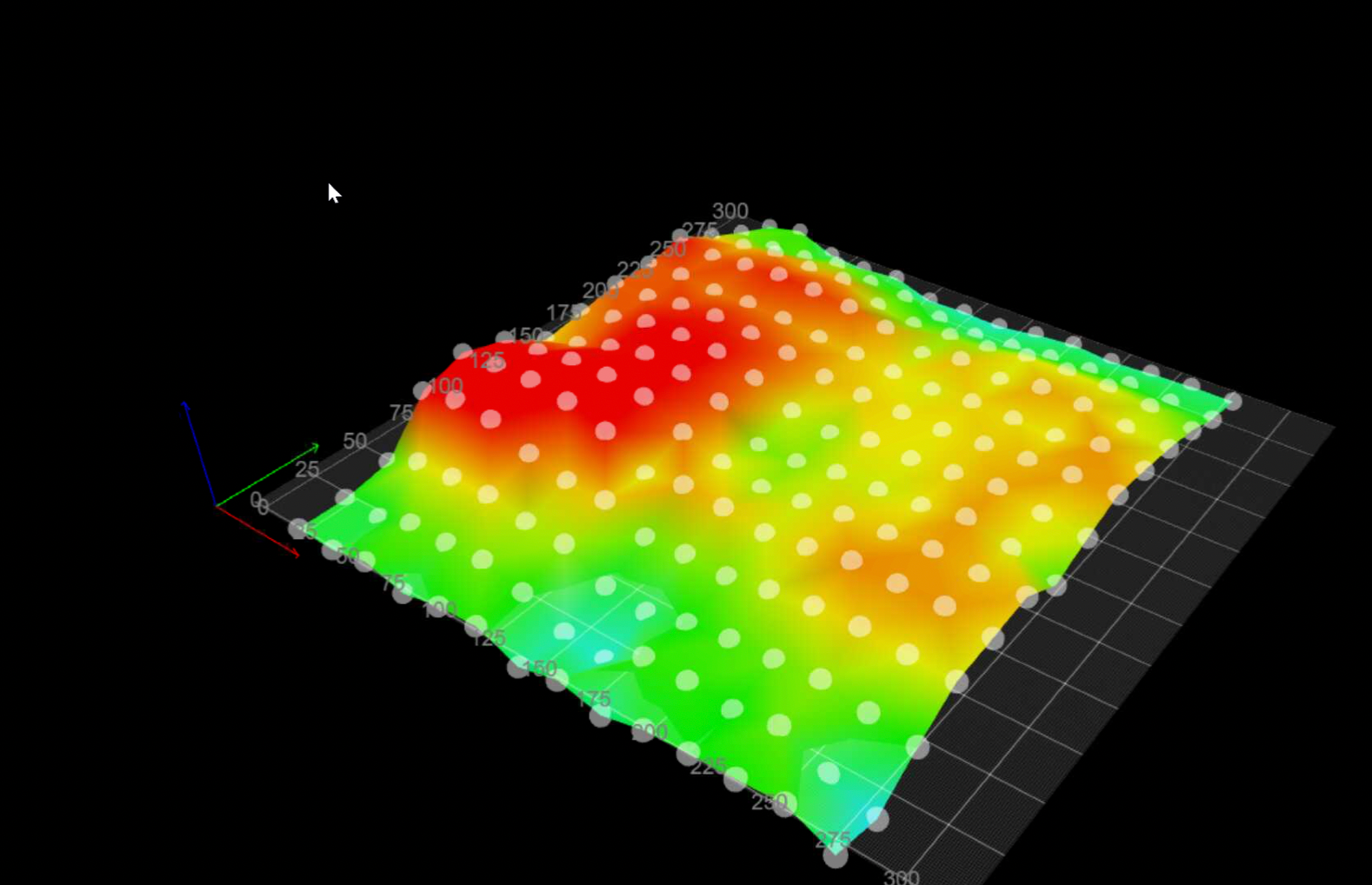
Heat Map:
Config Files:
download.zipStart gCode:
; Railcore 300ZL start code - 20 May 2021
M140 S[first_layer_bed_temperature] ; Raise bed temp to profile requested bed temp
M190 S[first_layer_bed_temperature] ; Wait for bed temp to rise
G28 ; home all axes
G32 ; Autocalibrate bed
G32 ; Autocalibrate bed a second time
G28 Z ; Home Z after bed leveling
G29 S1 ; Apply mesh bed leveling
;
G1 Z20 F600 ; Move bed down 20
M104 S[first_layer_temperature] T0 ; Raise hot-end temp to profile requested hot-end layer 1 temp
M109 S[first_layer_temperature] T0 ; Wait for hot-end temp to rise to profile requested hot-end layer 1 temp
;
G1 X0.0 Y0.0 Z1.0 F2000.0 ; prepare to prime
G92 E0 ; reset extrusion distance
G1 Z0.2 F600
G1 X60.0 E9.0 F1000.0 ; priming
G1 X125.0 E12.5 F1000.0 ; priming
G1 Z0.5 F600
G92 E0 ; reset extrusion distance
; end of start codeM122:

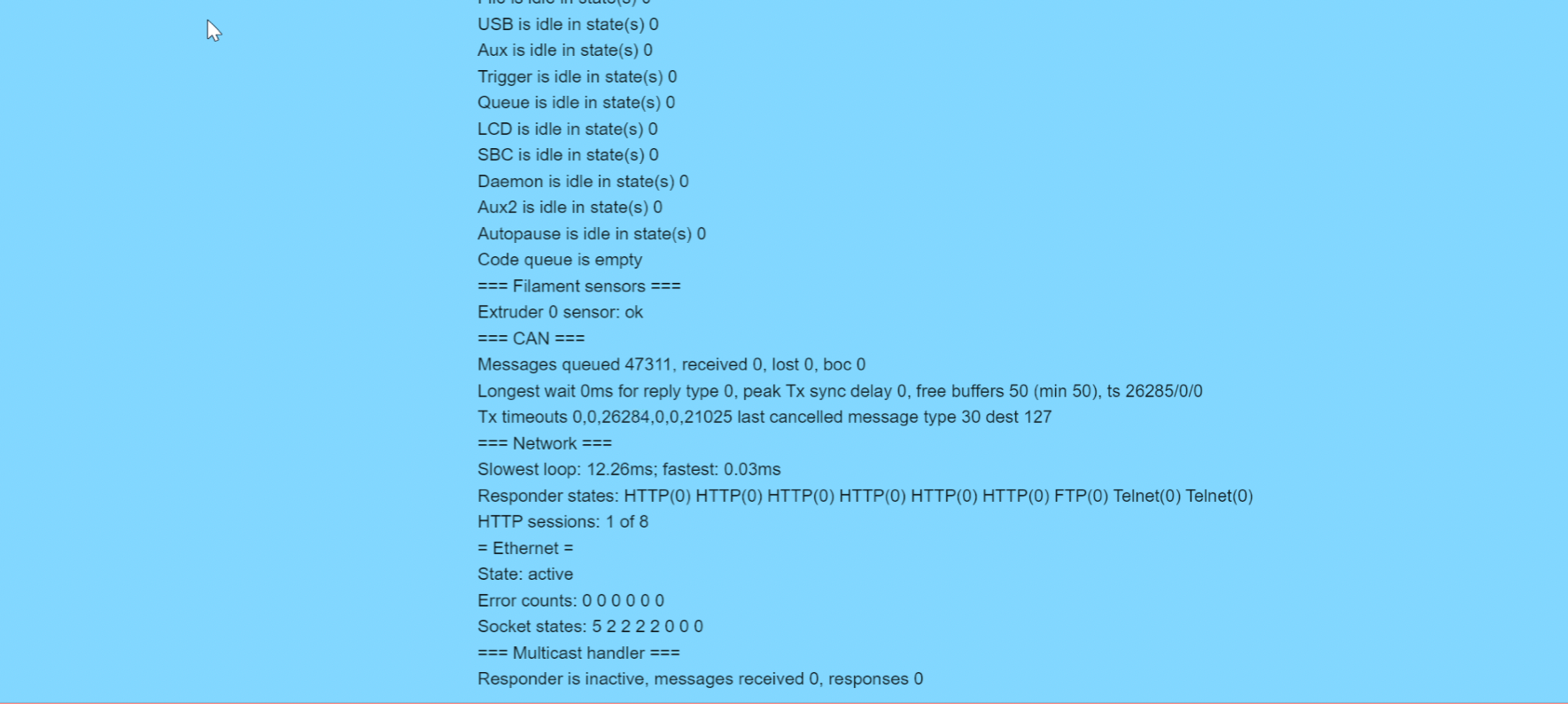
M98 P"config.g":

-
Mesh Bed Leveling expected behaviorposted in General Discussion
Hi.
My machine has started misbehaving, and I'm struggling to get good first layers. According to the height map I've generated, there are some low spots and some high spots in my bed.
I've run G29 S1 to load that map at the beginning of a job, but it doesn't seem like the printer is doing any actual compensation, as I get poor adhesion in the low spots and squeegeed out filament in the highs. (Is there anything else I'm supposed to do to get compensation?)
Anyway, trying to simplify the debugging I moved between a few points on the plate did a G0z0.51 (equivalent to a 0.020" feeler gauge). I'm not getting consistent gaps between the nozzle and the bed.
Should the map be applied to a random move like that outside a formal "print"? I would assume so, but we're in uncharted territory here for me.
Assuming it should, then something's not working right. Any ideas?
Thanks
-Ben -
RE: DWC Progress Questionposted in Duet Web Control
Heh, I guess so. Weird. I thought I updated everything correctly when I set this up a week ago, but I guess the DWC is still ancient.
Stand by...
-
RE: DWC Progress Questionposted in Duet Web Control
DWC 2.1.0
Board: Duet 3 MB6HC (MB6HC)
Firmware: RepRapFirmware for Duet 3 MB6HC 3.1.1 (2020-05-19b2)File:
https://www.dropbox.com/s/xfxyj7xei4st8up/Rebuild BLTouch Radius_0.1mm_PLA_.gcode?dl=0