Thermostatic servo control?
-
Can RRF do thermostatic control of a servo? That is, servo is one position when the designated temperature sensor is below a threshold, then moves linearly to a specified different position at an upper temperature value, then hold that all the time temperature is above that upper limit?
I don't find this listed as an option on the documentation gcode page.
My planned work around is to set up a fan output in RRF with a highish PWM frequency, connect that to a low-pass RC (i.e. convert it to an analogue signal) and then lash together an arduino-ish to read the analogue voltage and generate the necesary PWM.
I might instead try setting a lowish PWM frequency and try reading the pulse width directly, skipping the analogue stage. This seems to me probably slightly less reliable for the relatively low precision I'll need (to be honest, I probably just need on-off control swapping between two positions).
If a workaround is necesary, is there a better way I've overlooked?
-
depending on the granularity you need you might be able to generate the 1-2ms pulse directly from a fan output with a suitable pwm frewquency and limit the thermostatic control range to the range that gives you 1-2ms pulses.
-
@achrn could probbly be done with daemon.g
https://forum.duet3d.com/topic/14671/reprapfirmware-3-01-rc3-released :
I've just released this at https://github.com/dc42/RepRapFirmware/releases/tag/3.01-RC3. As well as fixing bugs in RC2, it provides the following new features:
- Additional 'daemon' GCode task, which repeatedly executes macro file daemon.g in the background (not yet available on Duet 3 with attached SBC, pending changes to DSF)
The way I see it, you configure your SERVO output and you configure your temperature probe and you do in daemon.g something like
; echo { heat.heaters[0].current } ; display current temp of heater 0
; echo { heat.heaters[1].current } ; display current temp of heater 1

if ( heat.heaters[1].current < 30 )
  M280 P0 S10                       ; below 30C keep at 10degrees
else
  M280 P0 S{10 + 3.5 * heat.heaters[1].current } ; set servo 0 to heater[1].current * 3.5 + 10 degrees

G4 P500  ; delay 0.5sec
and in your config something like
M950 S0 C"exp.heater3" ; create servo on heater3 pinand it should work
-
@bearer Thanks. I thought about that, but wasn't sure how to make the minimum pulse. I believe thermstatic control of a fan will switch it off at one extreme (ie fan control always runs between zero duty cycle and a specified maximum), so won't generate the nominally 1mS minimum pulse?
Possibly that won't matter if my servo hardware treats any pulse below the minimum it wants as a zero position, and I arrange the hardware so that exactly zero is the right position to be at one extreme - but I was planning on being lazy and not necesarily having phyical zero position on the servo being the homed position (i.e. the mechanical design might have a throw beyond where I actually want it to home to). I might be wrong about either of these assumptions.
-
I think M106 lets you specify min and max speeds; but its probably simplest to just try; or try arhi's suggestion not sure if daemon.g is any more risky with regards to safety if the firmware glitches or not.
-
@arhi Thanks, that works!
At least, this works (a throw of 0 degrees to 175 degrees over 5C) - after some time spent discovering it doesn't like blank lines in the file:
if { heat.heaters[1].current < 40 }
  M280 P1 S0;
elif { heat.heaters[1].current > 45 }
  M280 P1 S175;
else
  M280 P1 S{35 * ( heat.heaters[1].current - 40 )};
@bearer, I tried the pseudo-fan approach, and hit two problems. It seems to me that below the 'on' temperature the fan signal is zero regardless of the 'minimum' value set in M106, but it jumps immediately to that minimum when anything is demanded. That is, the 'minimum' seems to be the minimum non-zero value, not an actual minimum.
More significantly, I can't get thermostatic action to work right with a fan if I specify a maximum value. Ignoring servos entirely for now:
M950 F8 C"io7.out" Q50
M106 P8 H1 T40:50
This does what I think it should - I get a PWM duty cycle that varies from 10% at 40C on sensor 1 to 100% at 50C, e.g. (sensor 1 reading just under 49C):
M106 P8
Fan 8, speed: 100%, min: 10%, max: 100%, blip: 0.10, temperature: 40.0:50.0C, sensors: 1, current speed: 88%:
So then I try
M106 P8 H1 L0.30 T40:50This does what I think it should - I get a PWM duty cycle that starts at 30% at 40C (to 43C) then ramps to 100% at 50C, e.g. (sensor 1 reading just under 45C):
M106 P8
Fan 8, speed: 100%, min: 30%, max: 100%, blip: 0.10, temperature: 40.0:50.0C, sensors: 1, current speed: 49%:
However, when I introduce a X parameter, it goes wrong:
M106 P8 H1 L0.30 X0.60 T40:50Now, at 47C, when the linear interpolation from 40C to 50C should be giving me 70%, I only get 30%:
M308 S1
Sensor 1 type PT100 (MAX31865) using pin (spi.cs0,serial3.rx), reading 47.0, last error: success, 2/4 wires, reject 50Hz, reference resistor 400 ohms
M106 P8
Fan 8, speed: 100%, min: 30%, max: 60%, blip: 0.10, temperature: 40.0:50.0C, sensors: 1, current speed: 30%:
In fact, now I only ever get 0% (below 39C) or 30% (above 40C) (and hysteresis in the 39-40 range). I can't get any 'fan on' vlaue other than the 30%.
(And in all cases, what I'm actually seeing on an oscilloscope on the output is what the system reports I should be seeing, e.g. in the latest case, a 50Hz square wave with a 30% duty cycle.)
My application is controlling ventilation in an enclosure, so actually a bit of glitching is not a problem, and even if it fails entirely no houses burn down, so I'm relatively relaxed about that - I don't need five nines reliability.
Thansk for the suggestions.
-
don't forget to add G4 somewhere in the code of daemon.g
If I understand you correctly you are controlling the flaps on your enclosure to allow it to keep the enclosure temp between 40 and 45C. In that case 1sec update is more than ok, so something like
if { heat.heaters[1].current < 40 }
  M280 P1 S0;
elif { heat.heaters[1].current > 45 }
  M280 P1 S175;
else
  M280 P1 S{35 * ( heat.heaters[1].current - 40 )};
G4 S1 ; 1sec delay
I'd actually get it to 10sec delay
G4 S10as I doubt enclosure temp would vary more quickly than that so no need to overload cpu so S10
-
@arhi said in Thermostatic servo control?:
don't forget to add G4 somewhere in the code of daemon.g
https://github.com/Duet3D/RepRapFirmware/blob/v3-dev/WHATS_NEW_RRF3.md says " If the end of the file is reached, or the file is not found, it delays for 1 second and starts again." and that does seem to be what happens, in that the vent blades update position about once a second. So for a once per second-ish update you don't need a G4.
However, I agree a ten second update is probably more than often enough, and will add that when it's actually deployed. The chamber / enclosure isn't built yet - at the moment it's a servo-driven vent assembly on the benchtop.
40 to 45 is therefore just me testing the mechanism - if I sit the sensor on the heatsink on the Pi on the bench setup it rises to about 48, and if I take it off it falls to under 40 in a reasonable timeframe, so it's a useful range for testing.
-
@achrn said in Thermostatic servo control?:
If the end of the file is reached, or the file is not found, it delays for 1 second and starts again." and that does seem to be what happens, in that the vent blades update position about once a second. So for a once per second-ish update you don't need a G4.
Yes, but also somewhere in the forum or wiki I don't remember dc wrote that you should always have at least one G4 in that file so I kinda assume P500 or S1 is good to add, especially as you can really go much higher here

However, I agree a ten second update is probably more than often enough, and will add that when it's actually deployed. The chamber / enclosure isn't built yet - at the moment it's a servo-driven vent assembly on the benchtop.
Yes, of course, during testing period updating as often as possible is useful to speed up testing
 ... anyhow we understand each other and I guess you know how to proceed now
  .. good luck with the project! I plan to steel this idea of yours for my high temp build so I can allow air to escape if it gets too hot
-
i suppose you could also use the "fake" variables to keep track of the uptime and effectively runtime of the macro to dwell as needed or not needed if trying to keep to a fixed interval.
(i need to find time to play with this stuff now that I have pretty much all the parts for the i3 rework:)
-
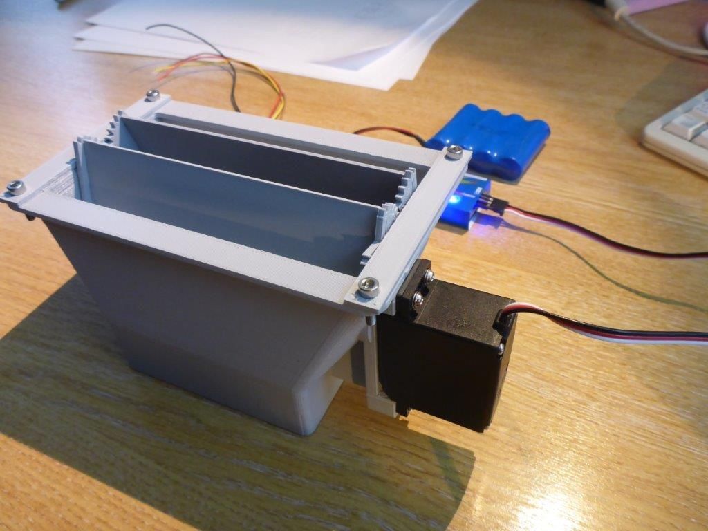
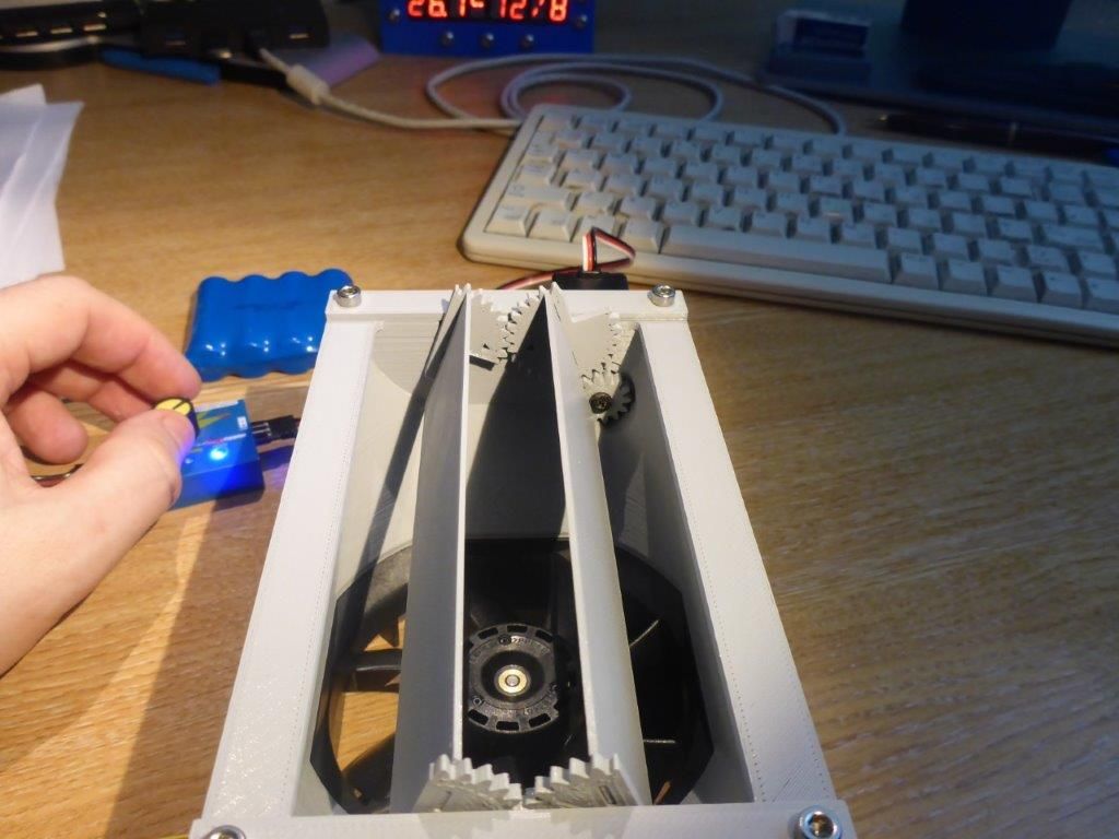
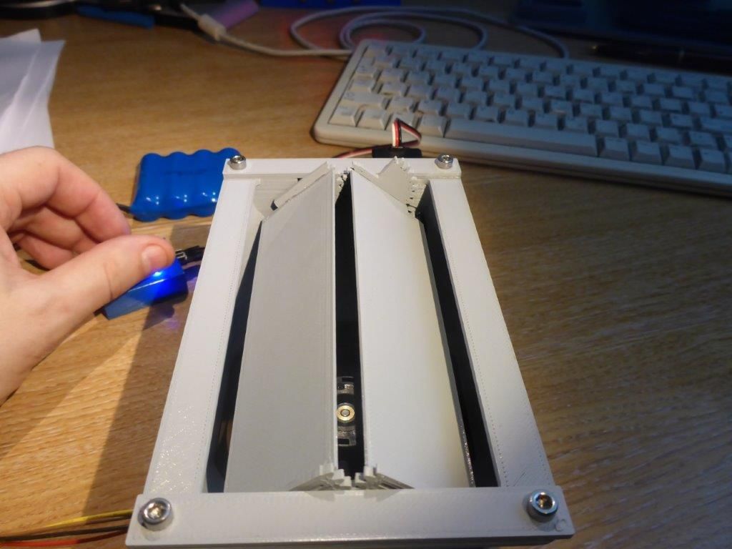
This is my prototype.
I've had problems with enclosure overheating before (at least, that's what I blamed my problems on), so I'm maybe oversensitive to it, but my thinking was an extract fan at the top of the enclosure could draw out hot air, but that a fan alone at the top of the enclosure would act as a chimney even when I wanted the air to stay put, so I wanted some means to block that convection.
However, I emphasise it's all just hypothetical speculation at the moment - the printer and enclosure isn't built yet.
Here it's just on a servo tester, but (as noted up the thread) I have had it running on the Duet.
This is printed in PLA - it would want something more robust for a high temperature enclosure, or your shutter blades would droop into the enclosure. You might be able to laser cut them from aluminium though and put a bolt through the gears as the pivot, if you want a decent temperature - they are three flat parts slotted together.


