Wiring a 3 pin end-stop switch a Duet3 6HC
-
Hello All,
I hope you are well. Over the last few weeks waiting for parts, I've finally converted my printer to use leadscrews on the vertical Z axis. So, now its time to add end-stops. I've not found a discussion on the 3 wire setup and need guidance on where to connect to the Duet 3 (1.0) MB. Looking at the board diagram doesn't seem to have 3 pin connectors highlighted for this purpose.
The end-stop I'm using is: https://openbuildspartstore.com/xtension-limit-switch-kit/ I has GND, V+, and SIG pins. Not at all sure where these should go. Any help is greatly appreciated.
Cheers, Jim -
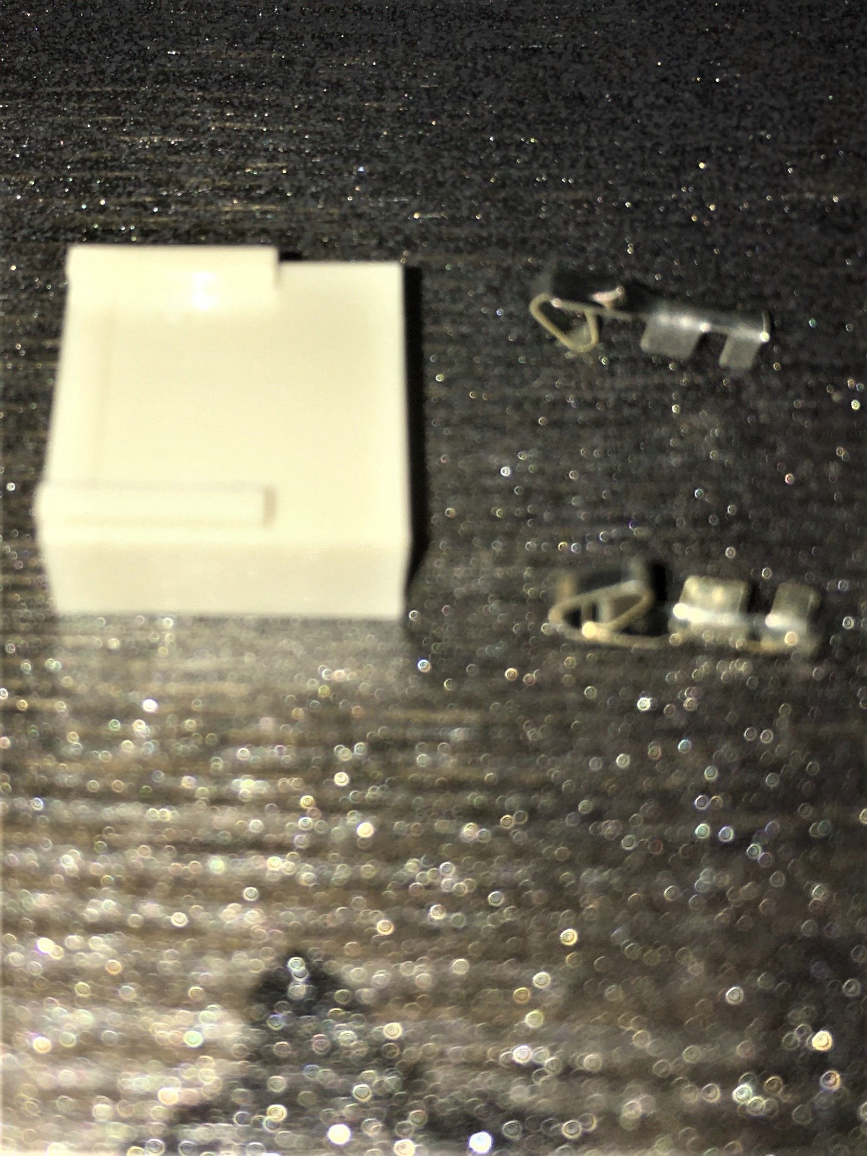
You'll want to use the general IO headers for this.
Choose one, I usually start with IO_1.
Connect 5V_ext to V+.
Connect Ground to Ground.
Connect the Signal pin to IO_X.in -
Thanks Lee, I'll give it a try and let you know how it goes.
-
should be similar to this https://duet3d.dozuki.com/Wiki/Connecting_endstop_switches#Section_Makerbot_Mechanical_Endstop_v1_Num_2 (which is the same wiring suggested above)
take note of inverting the pin name with f.ex
!io_1.inas for choosing which inputs to use you may want to refer to https://duet3d.dozuki.com/Wiki/Duet_3_Mainboard_6HC_Hardware_Overview#Section_IO to see if there are any features you'll want to keep for other things
-
Hi Lee and Bearer,
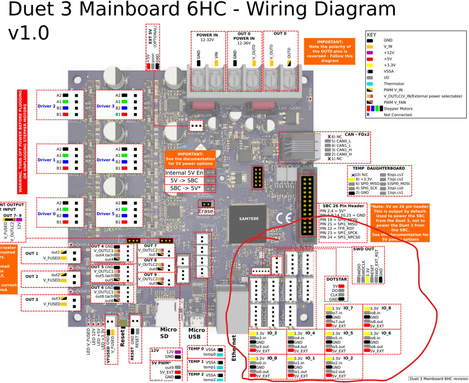
I'm curious to know if there are is a preferred direction when adding the pin connectors to the 5 pin block?
-
@Jim46 said in Wiring a 3 pin end-stop switch a Duet3 6HC:
is a preferred direction when adding the pin connectors to the 5 pin block?
oh yes, the little catch on the terminal should align to the hole on the reverse of the connector shell.
So the right and the bottom terminal in your pictures should slide in and lock in place.
-
Excellent!