Thank you Bearer, Danal, Droftarts, NexxCat et al for helping me get to this point. Was there one recent thing made the difference? Yes, I expect a steep learning curve on the set up since this a custom FDM style machine. I'll be going to the RepRap in a few minutes. Cheers!
Best posts made by Jim46
-
RE: Duet3D System won't turn on nowposted in General Discussion
-
RE: Duet3D System won't turn on nowposted in General Discussion
Hi Ian,
It was explained to me that my machine was too big for lead screws due to whip lash, so the whole machine is belt driven.
I'm going to open a new thread on commissioning a new custom machine.
Jim
Latest posts made by Jim46
-
RE: Proper Placement of Mechanical End Stopsposted in General Discussion
@bearer
Thanks Bearer! I'll be working it over the weekend. -
Proper Placement of Mechanical End Stopsposted in General Discussion
Hello All,
Making some progress wiring my end stops thanks to you!
If I understand correctly the Duet 3 6HC supports one end stop per axis.
So, if I want to put an end stop on the horizontal X-axis I can only have one. Then, what is the best practice? Put end stop at the far end away from the belt drive motor (NEMA23 Hi Torque in my case)? Next to the motor?
There are two leadscrews on the Z-axis with the motors pointing down. Can one use a end stop on each leadscrew? Again, place the end stop at the far end away from the motor? Or next to the motor?
I hope these comments are understandable.
Cheers,
Jim -
RE: Wiring a 3 pin end-stop switch a Duet3 6HCposted in General Discussion
Hi Lee and Bearer,
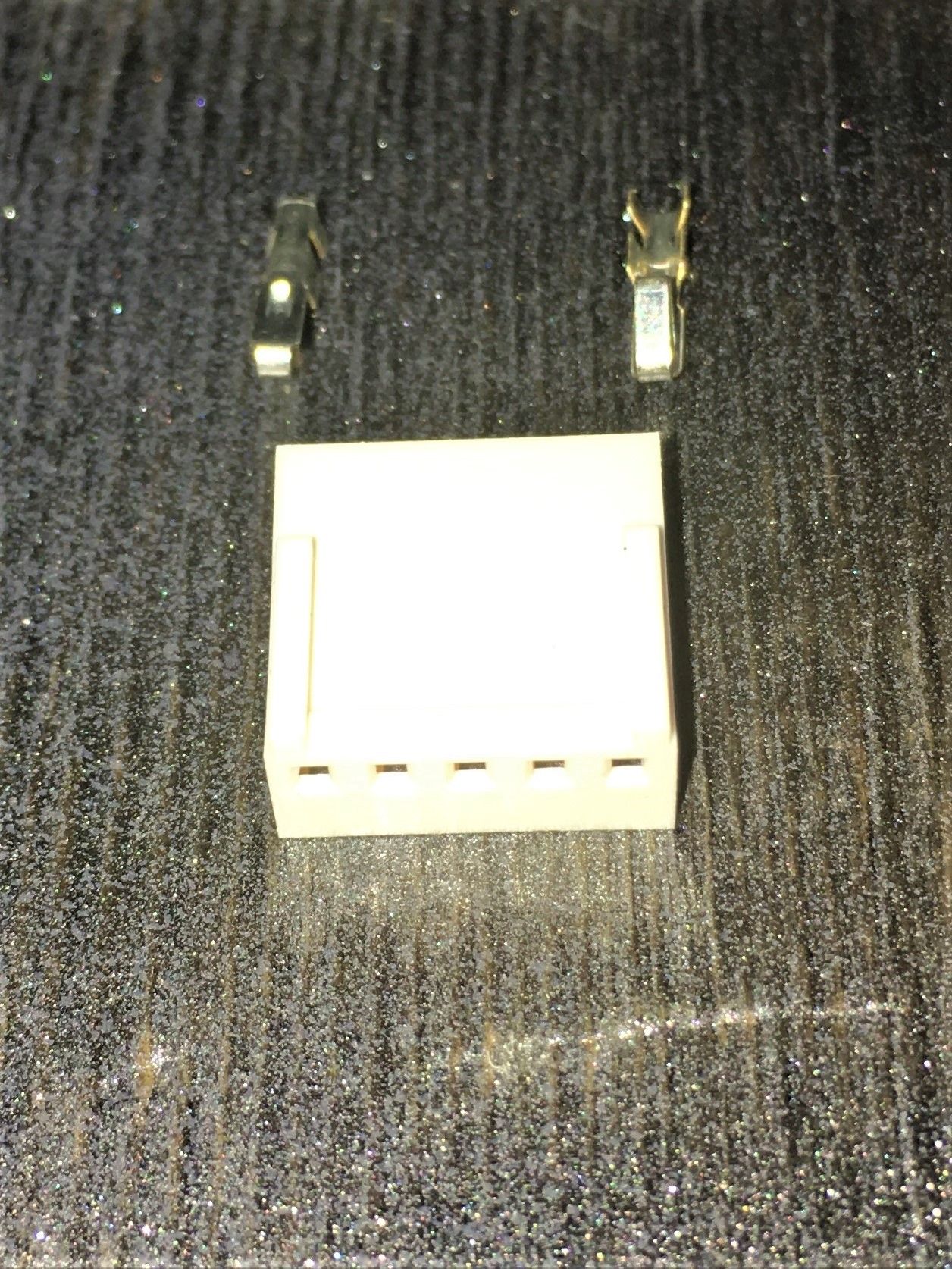
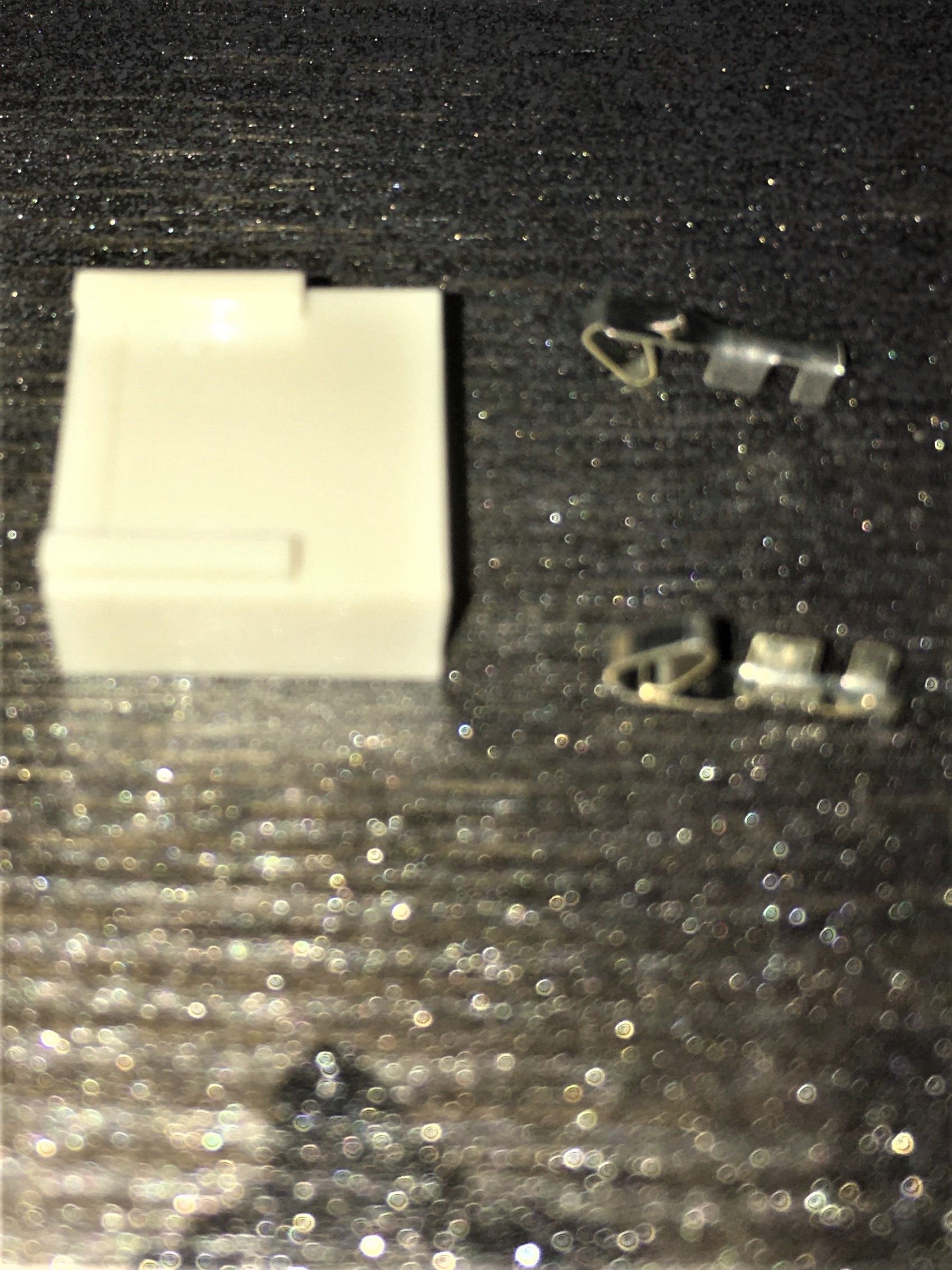
I'm curious to know if there are is a preferred direction when adding the pin connectors to the 5 pin block?

-
RE: Wiring a 3 pin end-stop switch a Duet3 6HCposted in General Discussion
Thanks Lee, I'll give it a try and let you know how it goes.
-
Wiring a 3 pin end-stop switch a Duet3 6HCposted in General Discussion
Hello All,
I hope you are well. Over the last few weeks waiting for parts, I've finally converted my printer to use leadscrews on the vertical Z axis. So, now its time to add end-stops. I've not found a discussion on the 3 wire setup and need guidance on where to connect to the Duet 3 (1.0) MB. Looking at the board diagram doesn't seem to have 3 pin connectors highlighted for this purpose.
The end-stop I'm using is: https://openbuildspartstore.com/xtension-limit-switch-kit/ I has GND, V+, and SIG pins. Not at all sure where these should go. Any help is greatly appreciated.
Cheers, Jim -
RE: How does one set up a Duet3D 6HC with RPi4 to wifi?posted in General Discussion
How does one set up a Duet3D 6HC with RPi4 to wifi?
-
RE: How does one set up a Duet3D 6HC with RPi4 to wifi?posted in General Discussion
Hmmm, not sure what happened, it seemed to mark it "unsolved". How do you change it to solved?
-
RE: How does one set up a Duet3D 6HC with RPi4 to wifi?posted in General Discussion
BTW, how does one mark a thread "SOLVED"?
-
RE: How does one set up a Duet3D 6HC with RPi4 to wifi?posted in General Discussion
Thanks you so much, I reset it as
M569 P2 S1... (Y1 motor) physical drive 2 goes forward
M569 P3 S0... (Y2 motor) Physical drive 3 goes reverse
M569 P4 S1... (Z1 motor) physical drive 4 goes forward
M569 P5 S0... (Z2 motor) Physical drive 5 goes reversealso used dual M584 lines x and Y and next line for Z and E
It is installed in the printer framce and it works! Thanks again!
Next is to design the extrustion head and design something to print out as a test.