Duet3D Logo Duet3D
    • Tags
    • Documentation
    • Order
    • Register
    • Login

    I have a question when wiring the servo i/o link.

    Scheduled Pinned Locked Moved
    Duet Hardware and wiring
    2
    3
    173
    Loading More Posts
    • Oldest to Newest
    • Newest to Oldest
    • Most Votes
    Reply
    • Reply as topic
    Log in to reply
    This topic has been deleted. Only users with topic management privileges can see it.
    • MRJEONundefined
      MRJEON
      last edited by

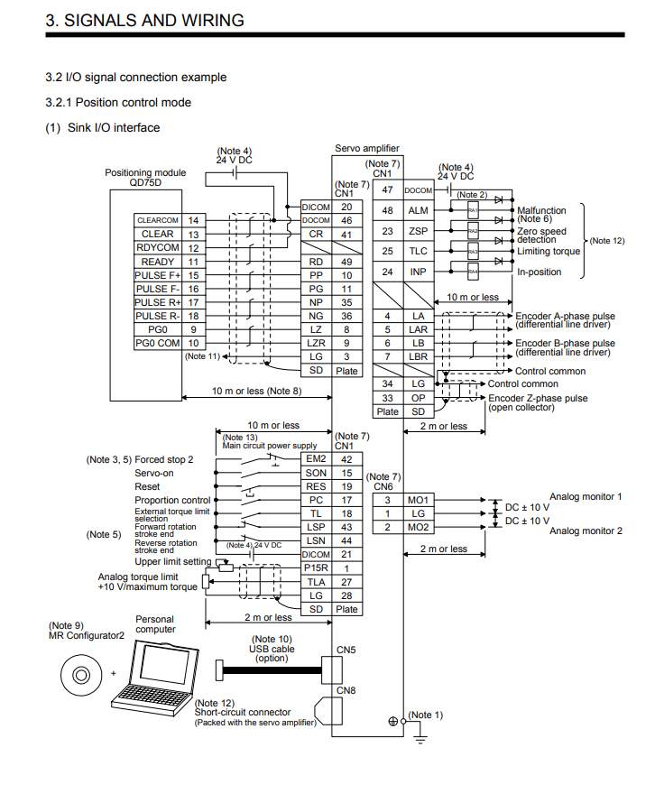
      Looking at the i/0 link in the current position control mode, there are additionally LZ, LZR, DOCOM, RES, SON, and ALM in PP, PG, NP, NG, but only 4 lines can be connected to DUET 2 EXPANSION BOARD. Where should the rest of the I/O LINK lines be connected?

      SERVO I,O LINK.png

      1 Reply Last reply Reply Quote 0
      • T3P3Tonyundefined
        T3P3Tony administrators
        last edited by

        I assume you are connecting this to a Duet 2 Expansion Breakout Board?

        We need more information on the dervo model (please link to the datasheet)

        It looks like this interface uses a pulse forward, pulse backward type of connection (also sometime called CW/CCW - clockwise, counter-clockwise) The Duet outputs step pulses and a direction signal - which is different.

        www.duet3d.com

        1 Reply Last reply Reply Quote 0
        • MRJEONundefined
          MRJEON
          last edited by

          parameter setting.png
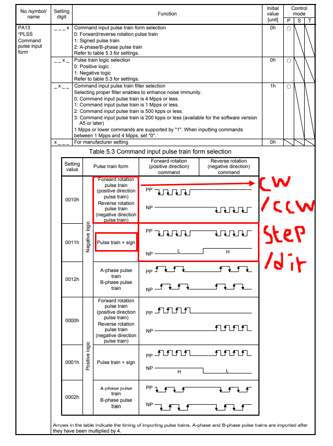
          In the manual of MR-J4-100A, there is a parameter setting.
          CW/CCW parameters and STEP/DIR parameters can be set.

          1 Reply Last reply Reply Quote 0
          • First post
            Last post
          Unless otherwise noted, all forum content is licensed under CC-BY-SA