True Bed Leveling
-
Looking at the pic the rails are inverted, the X/Y carriage hang down underneath?
this being so then the rail/extrusion needs to be lowered not raised, as from the height map that corner is showing the nozzle to be rising up
-
@CaLviNx said in True Bed Leveling:
Looking at the pic the rails are inverted, the X/Y carriage hang down underneath?
this being so then the rail/extrusion needs to be lowered not raised, as from the height map that corner is showing the nozzle to be rising up
Hmm...
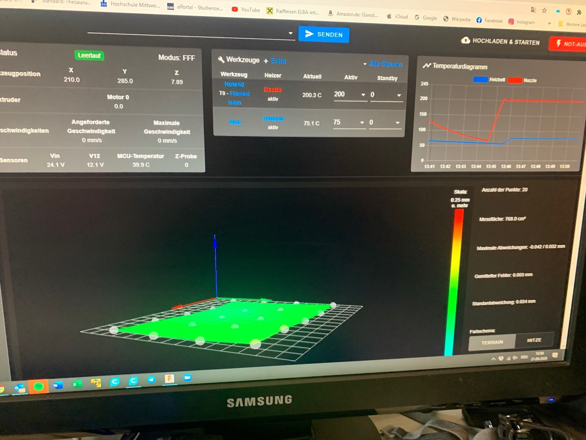
I just did a four point height map putting a metal plate along the front edge of the bed ensuring it was placed so that the probe triggered on it at both front corners.
The height map indicated that the front of the bed has higher than the back by the thickness of the plate.
So if "raising" the bed did that wouldn't lowering the front ends of extrusions/rails have the same effect?
Frederick
-
Your bed is warped. Auto-leveling isn't going to help here.
In the height map, look at the three points it uses as the true-leveling probe points. They are all near zero. So it's doing its job.
The docs say to have probe points near the leadscrews, but really you can have them anywhere and it'll do the least-squares best fit. I use 4 points at each corner and one point in the center and I think the result looks better than using just 3.
-
@CaLviNx said in True Bed Leveling:
@janjoh said in True Bed Leveling:
For "true bed leveling" you need three independant Z-motors.
He does have three independent Z-Axis Motors
Oh, I didn't see a screw at the third rail. Sooo I assumed two.. and that may very well have been a mistake on my part.
-
@janjoh said in True Bed Leveling:
@CaLviNx said in True Bed Leveling:
@janjoh said in True Bed Leveling:
For "true bed leveling" you need three independant Z-motors.
He does have three independent Z-Axis Motors
Oh, I didn't see a screw at the third rail. Sooo I assumed two.. and that may very well have been a mistake on my part.
My journeyman always drummed into me, : assume nothing, find out, assumption is the mother of all f**k ups
-
@TDK said in True Bed Leveling:
Your bed is warped. Auto-leveling isn't going to help here.
In the height map, look at the three points it uses as the true-leveling probe points. They are all near zero. So it's doing its job.
The docs say to have probe points near the leadscrews, but really you can have them anywhere and it'll do the least-squares best fit. I use 4 points at each corner and one point in the center and I think the result looks better than using just 3.
Really ? please tell me how can you be 100% of that without physically being there and laying the milled tool plate on a granite surface plate and physically measuring to see if it is warped or not, that's an amazing leap of faith and an assumption at best, I dont do assumptions, i prefer facts myself.
The usual "if it looks like sht, smells like sht, tastes like sh*t" applies, and the fastest thing to check would be if both y axis rails are perpendicular to each other, then and ONLY then start looking down other avenues, K.I.S.S applies. work methodically using a process of elimination to reach the reason for the anomaly, and dont take stabs in the dark without proof.
I would also advise the OP to remember to mentally separate the two features at work here.
We have "auto bed compensation" (G32) which is used to probe close to (in this case THREE) lead screws, that will work out to be a triangular pattern at THREE POINTS ONLY.
This is why you define the locations of the "lead-screws" using
M671: Define positions of Z lead-screws or bed leveling screwsAnd that G32 runs to make sure that all three screws in this case are in sync at the same height, that is true level.
Also remember Level does NOT equate to Flat, it only equates to LEVEL.
AFTER G32 has established a datum and "leveled" the three lead screws you then run (G29) "mesh grid COMPENSATION" THIS IS NOT leveling G32 ALREADY did that.
The purpose of G29 is to ascertain just how FLAT (or NOT) the print surface is.
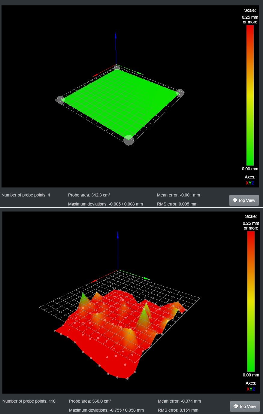
I have a picture of the exact same bed surface to illustrate.
The top picture is probed above the beds 4 adjusters and looks pretty much level.
The bottom picture is a multiple probe of a defined grid of the same bed immediately AFTER making sure it is level.
-
@CaLviNx said in True Bed Leveling:
Really ? please tell me how can you be 100% of that without physically being there and laying the milled tool plate on a granite surface plate and physically measuring to see if it is warped or not
I'm going off of this picture by OP:
@ErwinH78 said in True Bed Leveling:
in which you can see the bed is clearly non-planar. A warped frame or non-planar XY motion could also cause this.
Since bed leveling only adjusts the best fit plane, it's not going to remove the one corner that is warped upward.
-
You are correct Insofar as there is a rise at that point but from the picture you cannot assert what is causing it. So you cannot use the word warped with any degree of certainty.
-
@TDK said in True Bed Leveling:
in which you can see the bed is clearly non-planar. A warped frame or non-planar XY motion could also cause this.
Initially you said "Your bed is warped".
You seem to have amended your analysis.
Frederick
-
@fcwilt said in True Bed Leveling:
@TDK said in True Bed Leveling:
in which you can see the bed is clearly non-planar. A warped frame or non-planar XY motion could also cause this.
Initially you said "Your bed is warped".
You seem to have amended your analysis.
Frederick
Touché
-
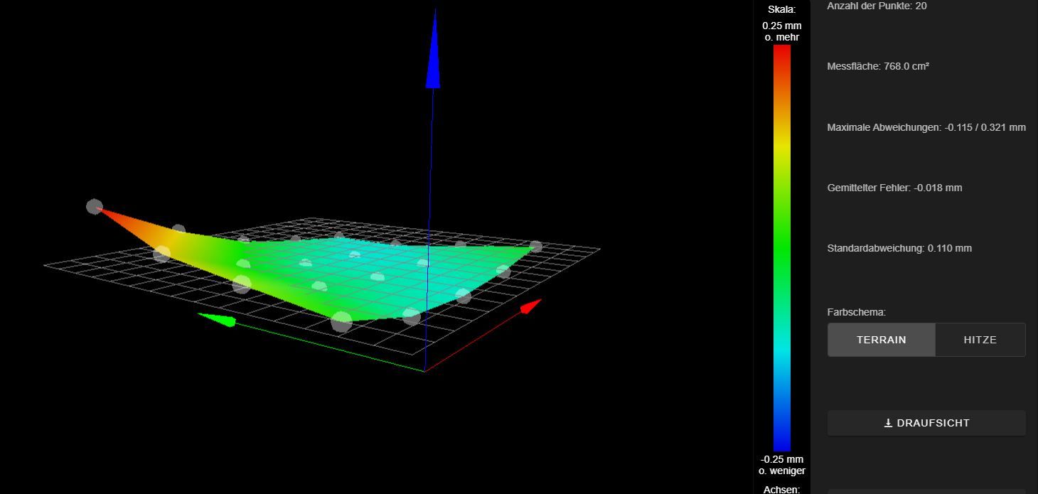
Hey Guys..... sorry for my late answer and thx a lot for help.
the issue was really caused by the Y-rails. i fixed that and with the result i´m very happy.
what do you think?

-
@ErwinH78 said in True Bed Leveling:
Hey Guys..... sorry for my late answer and thx a lot for help.
the issue was really caused by the Y-rails. i fixed that and with the result i´m very happy.
Glad to hear you got it working.
Frederick
-
@ErwinH78 said in True Bed Leveling:
Hey Guys..... sorry for my late answer and thx a lot for help.
the issue was really caused by the Y-rails. i fixed that and with the result i´m very happy.
what do you think?
Glad to see you got it fixed and glad to see the very flat milled tool plate was not warped as some fool tried to tell you.
-
@fcwilt said in True Bed Leveling:
@CaLviNx said in True Bed Leveling:
Looking at the pic the rails are inverted, the X/Y carriage hang down underneath?
this being so then the rail/extrusion needs to be lowered not raised, as from the height map that corner is showing the nozzle to be rising up
Hmm...
I just did a four point height map putting a metal plate along the front edge of the bed ensuring it was placed so that the probe triggered on it at both front corners.
The height map indicated that the front of the bed has higher than the back by the thickness of the plate.
So if "raising" the bed did that wouldn't lowering the front ends of extrusions/rails have the same effect?
Frederick
Sorry i didnt see your comment until now.
As you correctly pointed out that the frame is not "level"
The height map was showing that the rear of the LEFT Y axis rail was "higher" than the rear of the right one so that when the nozzle traversed closer to that point it (the nozzle) started to climb away from the bed which the graphic was showing happening.
Good practice would be to level the surface the printer is sitting (and built) on and then that way you know that when you assemble the frame it is going to be level with the surface it is on is already level, But in the real world that is not always possible.
Which is why i said to build using digital inclinometers zero'ed to the build surface, that means the printer will always be in sync with the build surface and that way zero will be relative zero relative to the surface the printer is sitting on, even if it isn't actually absolute zero but things will at least be perpendicular and parallel to the surface the printer will spend its life on.
Unless of course you have adjustable feet on the printer you can then set everything to absolute zero